[0015]Advantageous effects of the invention are described hereinafter by substituting an aluminum alloy product for the light metal product, and the basically same thing can be said in the case of a
magnesium product. The present invention is the same as Japanese Patent No. 2954476, and U.S. Pat. No. 5,739,498, disclosing the method using the pin (
retainer piece) made of the iron-
base metal, in that the rivet made of the iron-base metal is used, and the iron—iron similar metals, such as the rivet and the steel product, are spot-welded with each other.
[0016]However, a first point where the present invention largely differs from those conventional technologies lies in that the light metal product and the iron-base rivet are connected with each other beforehand in the previous process (a separate process) preceding the spot welding as described in the requirement “a”, instead of supplying the iron-base rivet to the tip of the electrode at the time of spot welding, and embedding the iron-base rivet into the aluminum alloy product with the use of the electrode. More specifically, the stem of the iron-base rivet is embedded into the position of a spot of the aluminum alloy product, corresponding to spot welding, in the previous process preceding the spot welding, such as, for example, at the time of press forming of the aluminum alloy product. By so doing, it is possible to overcome unrealistic aspects and limitations of the conventional technologies whereby the iron-base rivet is supplied to the tip of the electrode at the time of spot welding, and the iron-base rivet is further embedded into the aluminum alloy product by the electrode to thereby eliminate the constraint on, and the problem with the conditions applicable to the spot welding, so that spot welding between the iron—iron similar metals, such as the rivet and the steel product, is enabled.
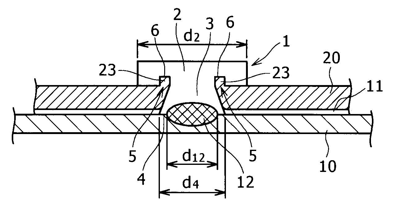
[0017]Further, a second point where the present invention largely differs from those conventional technologies lies in that upon joining the light metal product with the rivet, the stem of the rivet is driven into the position in the light metal product, corresponding to spot welding between the light metal product and the steel product, and upon driving the rivet, while the light metal product is blanked out by the stem of the rivet, the tip of the stem of the rivet is penetrated through the light metal product toward the side thereof, for connection with the steel product, as described in the requirements “c”, and “d”, respectively. By doing so, evenness of a contact face between the iron-base rivet, and the steel product, for spot welding with the steel product, together with a rivet-driven potion of the aluminum alloy product, is ensured. If the iron-base rivet is simply embedded in the aluminum alloy product, as is the case of the conventional technologies, the aluminum alloy product as pressed by the embedded iron-base rivet will undergo deformation, thereby forming a protruded part thereof, jutting out toward the steel product. As a result, evenness required of
superimposition of a spot (the contact face with the steel product) in the aluminum alloy product, penetrated by the iron-base rivet, stacked upon the steel product, will be considerably interfered with. In this connection, the evenness refers to evenness required of the
superimposition (a stacked layer) of the spot in the aluminum alloy sheet 20, penetrated by the iron-base rivet, upon the steel product, and evenness required for the joining by the spot welding. With the present invention, needless to say, unevenness to a degree, tilt, an arc, and so forth are tolerable if the
superimposition (the stacked layer) of the aluminum alloy product upon the steel product, and joining by the spot welding can be carried out.
[0018]Still further, a third point where the present invention largely differs from those conventional technologies lies in that the aluminum alloy product is clinched with the iron-base rivet embedded beforehand as described in the requirement “e”, and further, such connection by clinching of the aluminum alloy product with the iron-base rivet (mechanical connection) is added to the spot welding between the iron—iron similar metals, such as the rivet and the steel product, at the same connection spot, thereby obtaining a high joint strength due to the synergistic effect of those connections.
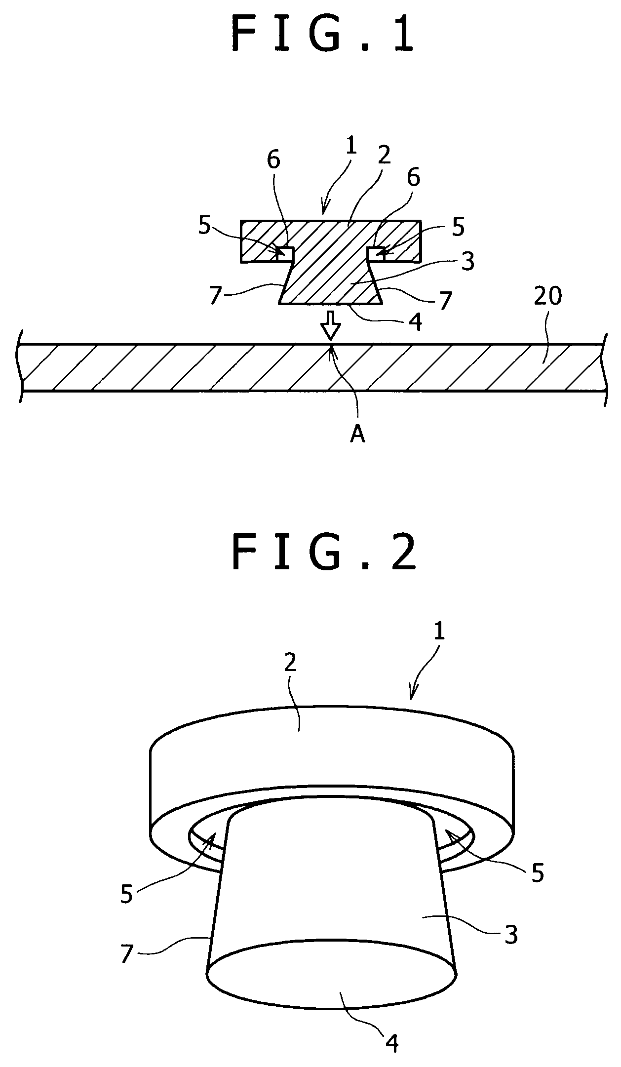
[0019]In order to cause the aluminum alloy product to be clinched with the iron-base rivet embedded beforehand, it is insufficient to simply embed the iron-base rivet in the aluminum alloy product, but there is the need for introducing a novel idea to the shape of the iron-base rivet, such as, for example, formation of the cavity for clinching the aluminum alloy product in the outer
peripheral surface of the iron-base rivet as described in the requirement “b”.
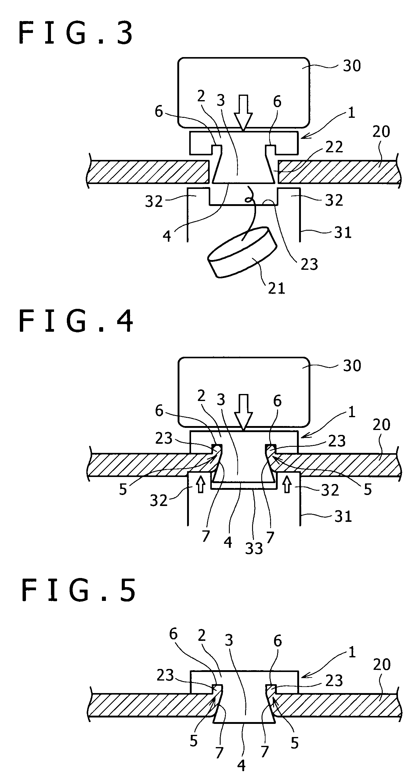
[0020]In order to effectively drive the rivet so as to actually satisfy all those conditions, it is necessary to carry out press forming using dies. More specifically, there is the need for pressing the head of the rivet from the upper side, and a lower die for pressing the aluminum alloy product from the underside thereof. It is evident from this that with those conventional technologies whereby the iron-base rivet is embedded into the aluminum alloy product simply by the electrode, the aluminum alloy product cannot be clinched. Further, it is evident that there is no possibility at all that the aluminum alloy product can be clinched with the iron-base rivet within the same process where the spot welding is carried out, so that there is the necessity of connecting the iron-base rivet with the aluminum alloy product beforehand in a previous process (separate process) preceding the spot welding.

