[0010]Since embodiments of the invention utilise electronically steered antennas, the antenna stares at, rather than glides past, the target and surrounding clutter. This means that the spectral spreading of static ground clutter associated with mechanical radar systems can be eliminated, overcoming one of the shortcomings of mechanical radar systems that would otherwise render a crawler radar system unsuitable for
Doppler processing.
[0013]This relative increase in duration of target-stare means that a proportionately greater number of data are collected by the
receiver, enabling the
receiver to increase the Doppler and
range gate resolutions. This increased range resolution reduces the
relative power of the clutter within a given
range gate and the increased Doppler resolution improves the ability to separate returns from targets from clutter in the Doppler domain. Both improvements have the effect of improving the
signal to
noise ratio (SNR).
[0014]Preferably, the receiver includes a
low frequency blocking filter and a Doppler processor for deriving
Doppler frequency data: the
low frequency blocking filter is arranged to identify an average magnitude of said signals received from a target and to subtract the identified average magnitude from respective said signals prior to
Doppler processing. Preferably the
low frequency blocking filter operates on data output from a Range FFT and the Doppler processor is a Doppler FFT. The blocking filter has the effect of removing the
energy component in the zero order Doppler FFT bin that is attributable to stationary clutter, and it advantageously removes clutter components that would otherwise be spread to adjacent bins as part of the post-
processing windowing of the processed data. Since, for ground-based radar the amplitude of this stationary clutter tends to be large (relative to the
signal from the target), removal of this clutter improves the
visibility and detectability of small, low-speed targets such as those characterised in the background section. In addition, the increased Doppler resolution means that the spectral spreading caused by windowing (which is independent of the length of the Doppler FFT) is reduced in
absolute frequency terms.
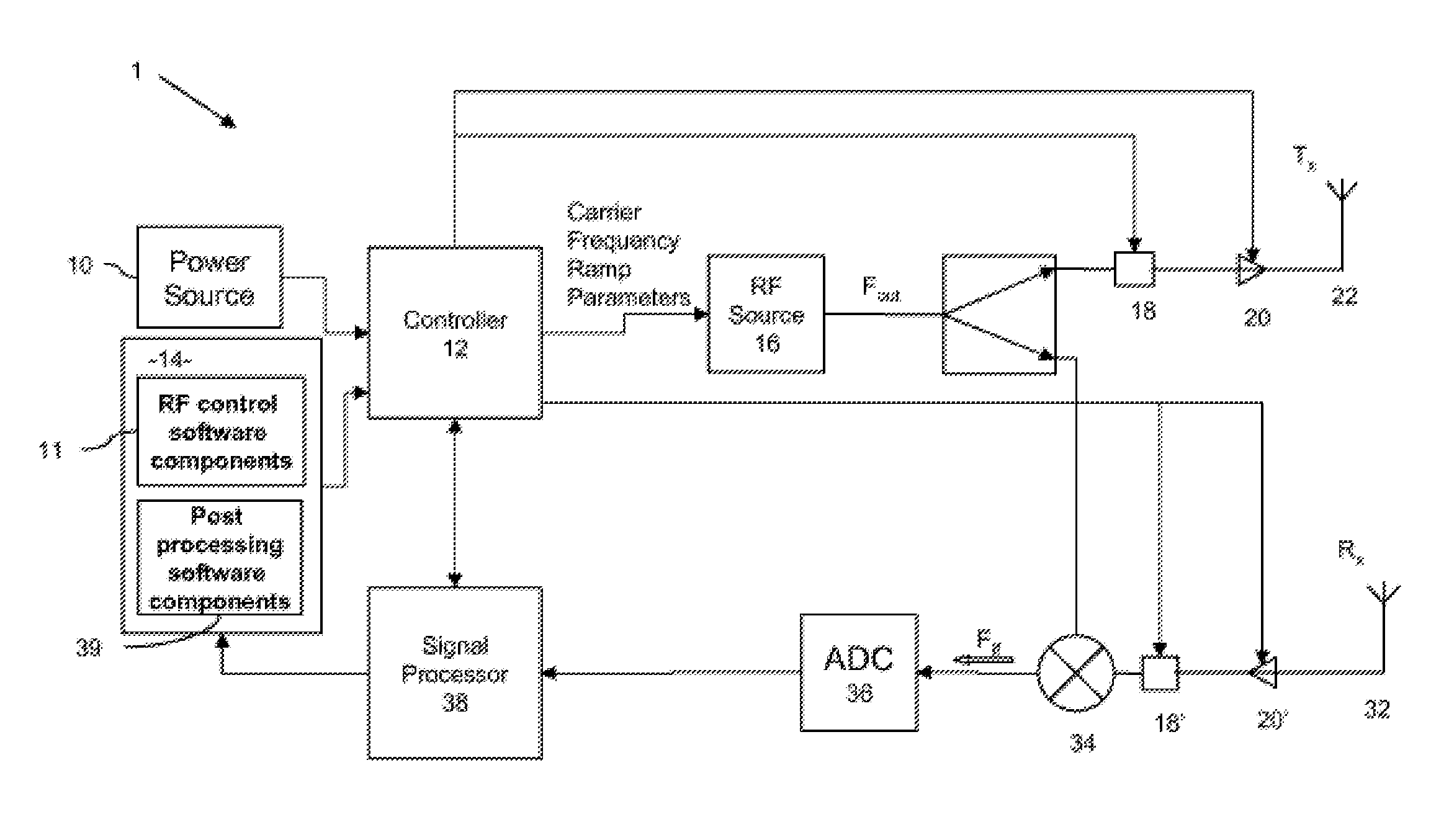
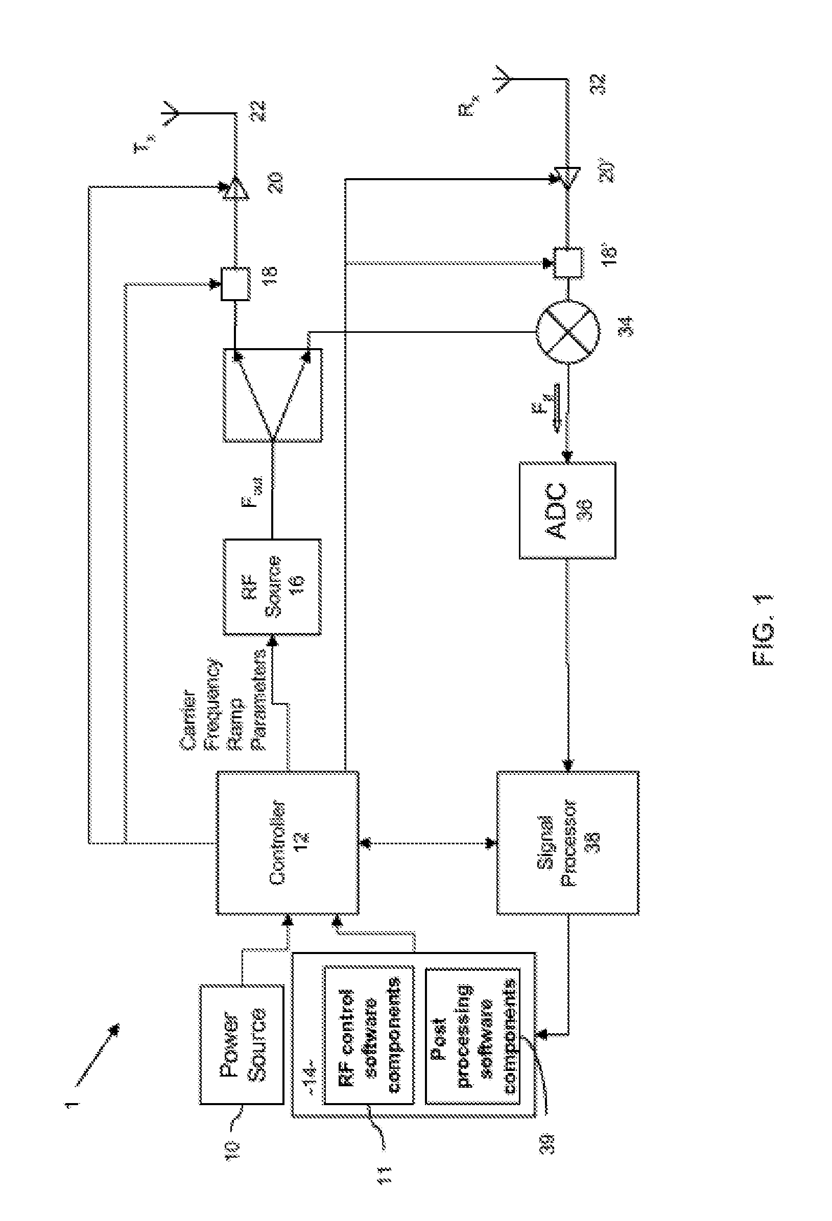
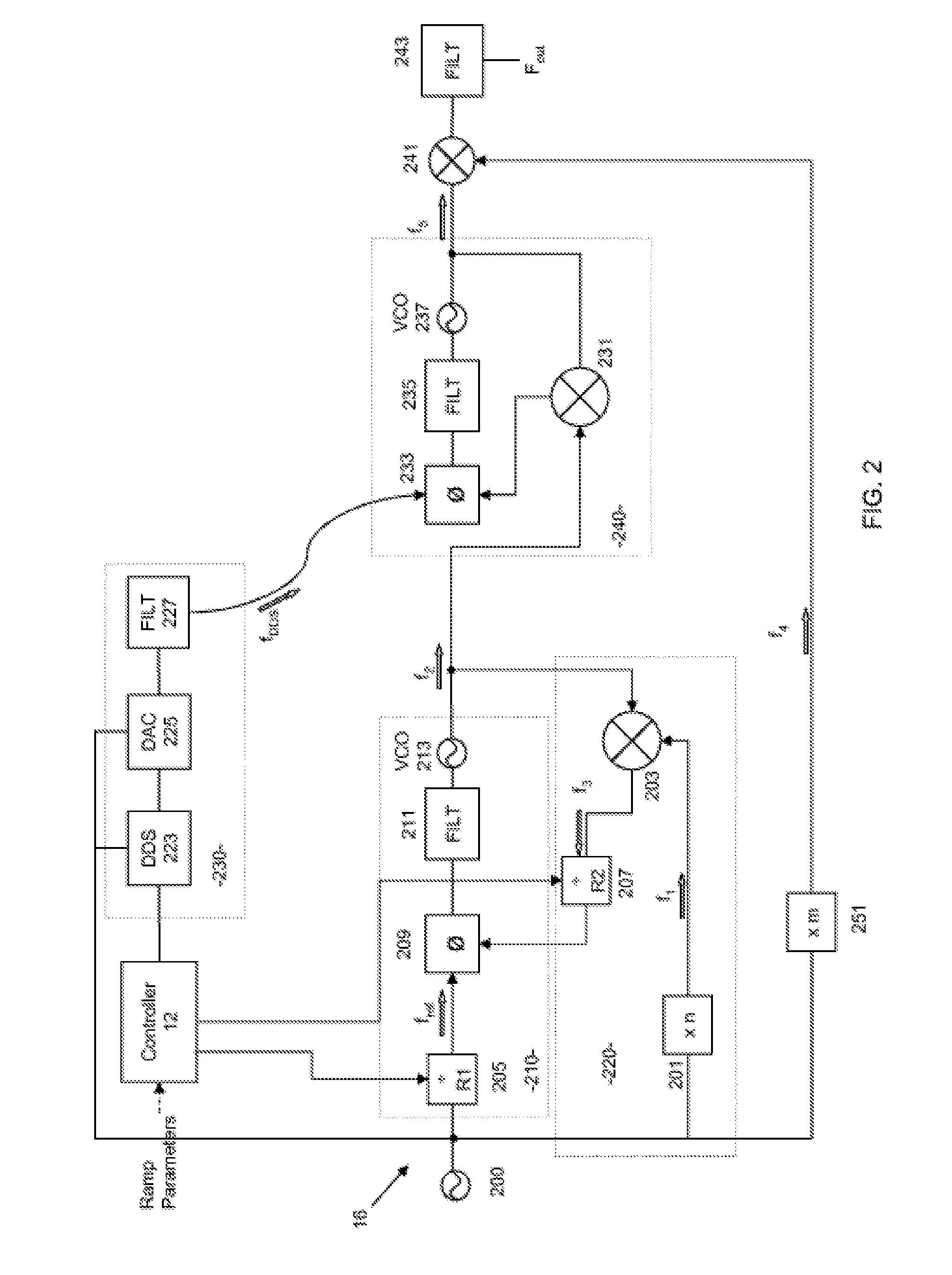
[0015]For the case where the electronically steered antenna is embodied as a frequency scanning antenna, the radar system incorporates a frequency source that minimises the amount of
phase noise in the
signal, so as to reduce the oscillator-dependent spreading around returns. Most known synthesisers utilise a
fixed frequency source (e.g. in the form of a
crystal oscillator), which, in order to generate a range of frequencies, are integrated with a circuit that includes a
phase detector, frequency dividers and a
variable frequency oscillator (conventionally referred to as
Phase Locked Loop Synthesisers). Such variable frequency oscillators inherently have a certain amount of
phase noise (typically referred to as
dither) in the output signals, and
phase locked loop synthesisers multiply up the signal received from the
signal generator, including the
noise. As a result, a signal with a significant amount of
dither, when reflected from a stationary target, can confuse the
signal processing components and appear as a moving target. Preferably, therefore, the frequency generator is embodied as a
digital signal generator that minimises the amount of multiplication of a given signal, thereby incurring substantially less
phase noise than that generated by conventional signal generators. In addition, this means that phase locked loops of signal generators embodied according to the invention are capable of operating at higher loop frequencies than is possible with conventional arrangements.
[0018]In one arrangement the radar system is arranged to transmit data indicative of
radiation received and processed thereby to a remote
processing system for display, review and interpretation at the remote
processing system instead of at the radar system, thereby further reducing the processing and control components required by the radar system. Advantageously, and as will be appreciated from the foregoing, since a radar system according to this aspect of this invention is neither bulky nor heavy, it readily lends itself to portability.

