Polarization preserving front projection screen material

a technology of polarization preservation and front projection, applied in the field of front projection screens, can solve the problems of poor polarization preservation, erode the quality of the experience, and create eye fatigue, and achieve the effects of improving light control, enhancing brightness, uniformity and contrast, and maintaining the optimum gain characteristics

Active Publication Date: 2009-12-03
REAID INC
View PDF21 Cites 20 Cited by
  • Summary
  • Abstract
  • Description
  • Claims
  • Application Information

AI Technical Summary

Benefits of technology

[0010]This disclosure pertains to engineered reflective diffusers, and in particular to screens used in front projection systems. The screens provide optimum polarization preservation for stereoscopic 3D viewing, as well as improved light control for enhanced brightness, uniformity, and contrast for both 2D and 3D systems. The present disclosure seeks to direct light where it is desired, while maintaining optimum gain characteristics.
[0011]According to the present disclosure, an engineered surface is used to optimally disperse illumination light into a range of viewing angles, within a specific diffusion locus, with suitable gain profile, while optimally preserving polarization. Such a screen, when combined with matched polarization analyzing eyewear, provides extremely low cross-talk from any observation point.
[0014]According to another aspect, a set of design rules are used to produce a generating function for the surface topography. The generating function provides the fundamental building blocks of the microstructure (comprising either one or a plurality of generating kernels), which carries with it the (macroscopic) ensemble statistics of the desired diffuser. Such a design can have superior uniformity in appearance, because it is statistically complete at the fundamental dimension. The design rules further provide for substantially only single reflections within a prescribed diffusion locus. The diffusion locus is defined in accordance with the angular extremes in illumination and detection / observation. In yet further design rule considerations, the generating kernel can provide a specific intensity distribution (e.g. Lambertian) within the diffusion locus, with a prescribed angular decay in intensity at the boundary of the diffusion locus. In a preferred embodiment that maximizes light efficiency, this decay is represented by a step function.

Problems solved by technology

This cross-talk is manifested as a “ghost image,” which erodes the quality of the experience and creates eye fatigue.
Owing to the statistics of the surface roughness of such known screens, they have very poor polarization preservation and poor effective light efficiency (i.e., while total integrated scatter, or TIS, is high, utilization of light in angle space is poor).
Such statistical surfaces provide limited control of screen gain profile, directionality, and polarization.
Moreover, coating processes frequently show resolvable structures (e.g. sparkle), and uniformity problems, such as textures.
Such “silver screens” are frequently delicate, and are not able to withstand a mild abrasive cleaning process.
Lambertian screens provide uniform appearance in observed brightness, but make poor use of projection light.
That is, a significant portion of incident light is scattered outside of the field of view, reducing system efficiency.

Method used


Image

  • Polarization preserving front projection screen material
  • Polarization preserving front projection screen material
  • Polarization preserving front projection screen material

Examples


Embodiment Construction

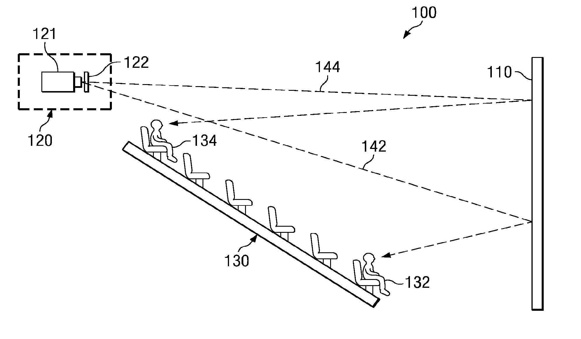
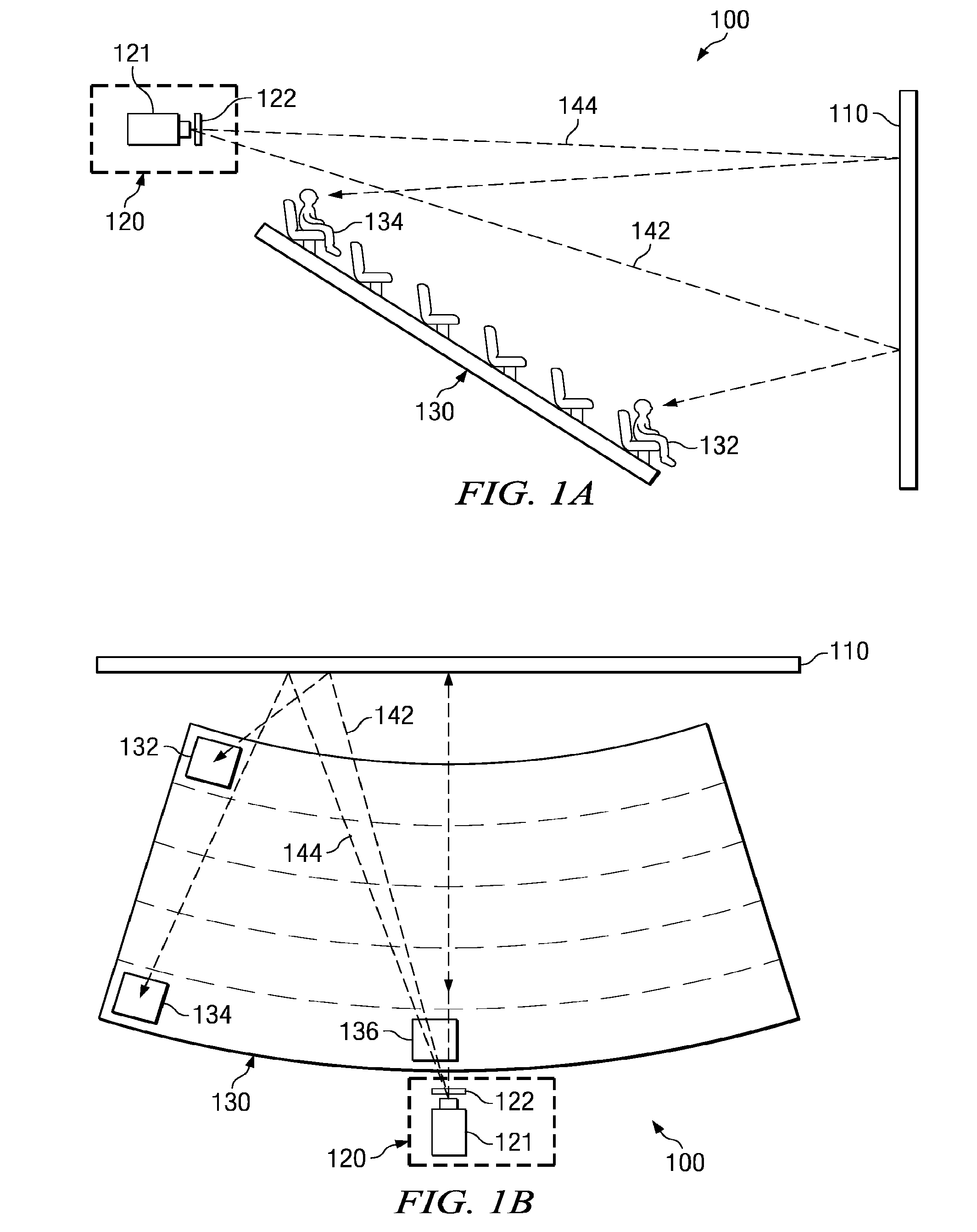
[0059]FIG. 1A is a schematic diagram illustrating a side view of a typical movie theatre 100 and FIG. 1B is a schematic diagram showing a top-down view of a movie theatre 100. Movie theatre 100 includes a reflective screen 110, a projector platform 120, and a viewing area 130. Projector platform 120 may include projector 121 and polarization switch 122. Viewing area 130 may provide seats organized in rows away from the screen, defining a viewing area or viewing for viewers that may sit (or stand) in different places within the viewing area 130. For instance, a first viewer may be located at the front-left viewing position 132 of the movie theatre 100, and receive reflected light 142. A second viewer may be located at the rear-left viewing position 134 and receive reflected light 144. A third viewer be located in a central viewing position 136.

[0060]With recent developments of polarization technology, there has been a resurgence of three dimensional movies, decoded with matched eyewe...


PUM

PropertyMeasurementUnit
lengthaaaaaaaaaa
wavelengthaaaaaaaaaa
vertical offset angleaaaaaaaaaa

Abstract

Polarization preserving front projection screens and diffusers provide optimum polarization preservation for stereoscopic 3D viewing, as well as improved light control for enhanced brightness, uniformity, and contrast for both 2D and 3D systems. Generally, the disclosed screens direct light from a projector toward viewers within a diffusion locus, while maintaining optimum gain characteristics. More specifically, light incident on a region of the front projection screen from a predetermined projection direction is reflected by an engineered surface to a predetermined diffusion locus after undergoing substantially single reflections. The engineered surface, comprised of generating kernels, is used to optimally diffuse illumination light into a range of viewing angles, within the diffusion locus, with suitable gain profile, while optimally preserving polarization for 3D applications. Such a screen, when combined with matched polarization analyzing eyewear, provides extremely low cross-talk from any observation point.

Description

CROSS-REFERENCE TO RELATED APPLICATIONS[0001]This patent application is a divisional of non-provisional patent application Ser. No. 12 / 361,532 entitled “Polarization preserving front projection screen,” filed Jan. 28, 2009, which relates and claims priority to provisional patent application 61 / 024,138, entitled “Polarization Preserving Front Projection Screen,” filed Jan. 28, 2008, which are herein incorporated by reference for all purposes.BACKGROUND[0002]1. Technical Field[0003]This disclosure generally relates to the front-projection screens and more specifically relates to front projection screens that optimally manage the diffusion of light such that polarization is preserved. Such screens may additionally maximize image brightness and contrast subject to specific projector and observation angles.[0004]2. Background[0005]In stereoscopic 3D systems utilizing passive polarization analyzing eyewear, the screen is an integral part of the system. Any depolarization occurring at the ...

Claims


Application Information

Patent Timeline
Patent Type & Authority Applications(United States)
IPC IPC(8): E04F13/00G02B30/25
CPCG02B27/26G03B21/60Y10T428/24802G03B35/26G03B35/16F16H21/14G02B30/25Y10T74/18232G03B21/00G03B21/56
Inventor COLEMAN, DAVID A.SHARP, GARY D.
Owner REAID INC
Why Eureka
Try Eureka