Method and apparatus for treating wastewater

a technology for treating wastewater and reactors, applied in the direction of settling tank feed/discharge, water treatment compounds, sedimentation settling tanks, etc., can solve the problems of increasing the size of the reactor and/or the use of additional agitation power, increasing investment and operating costs, and difficult process control

Active Publication Date: 2009-12-10
VEOLIA WATER SOLUTIONS & TECH SUPPORT
View PDF14 Cites 16 Cited by
  • Summary
  • Abstract
  • Description
  • Claims
  • Application Information

AI Technical Summary

Benefits of technology

[0010]Accordingly, the invention aims to provide a flocculation reactor which, thanks to one or more agitators and the delimitation of areas with different levels of agitation, improves the kinetics of the reaction between a raw fluid to be treated and a flocculating agent (and where applicable a granular material forming a flocculation ballast), increases the usable fraction of the volume of the reactor and reduces the risk of bypassing the process (i.e. the risk of no circulation occurring in the areas with different levels of agitation), with a moderate level of the power devoted to the agitation levels.
[0011]The invention further aims to provide a method of treating a raw fluid to be treated by flocculation and separation, the method combining, within the overall dimensions of a single vat, two areas with different levels of agitation, and maximizing the turbulence for a given energy level and for a given contact time.

Problems solved by technology

The possible existence of a bypass (short circuit) between the vat inlet and outlet and the fact that in practice use of the volume of the vat is incomplete, as is easily demonstrated by mathematical modeling linked to physical models, usually lead to increasing the size of the reactors and / or to the use of additional agitation power.
This induces an increase in the investment and operating costs, however.
Furthermore, it is standard practice to have the inlet and the outlet of a given vat at the greatest possible distance from each other, for example by using a low-level inlet at one end of the vat and a high-level outlet at the other end, although this proves to be a problem if it is necessary to connect a plurality of vats in series.
In fact the above document also mentions, for historical reasons, a cruciform baffle formed of two vertical walls mounted on the bottom of the vat, near the agitator, but indicates that the process is then difficult to control and the circulating liquid rapidly becomes contaminated with solid particles.
It also indicates that these walls induce an increase in power consumption.
The screw produces just sufficient turbulence to maintain the solids in suspension without shearing them, which can lead to slow mixing and therefore degrade performance.

Method used


Image

  • Method and apparatus for treating wastewater
  • Method and apparatus for treating wastewater
  • Method and apparatus for treating wastewater

Examples


Embodiment Construction

[0090]Objects, features and advantages of the invention emerge from the following description, which is given by way of illustrative and nonlimiting example and with reference to the appended drawings, in which:

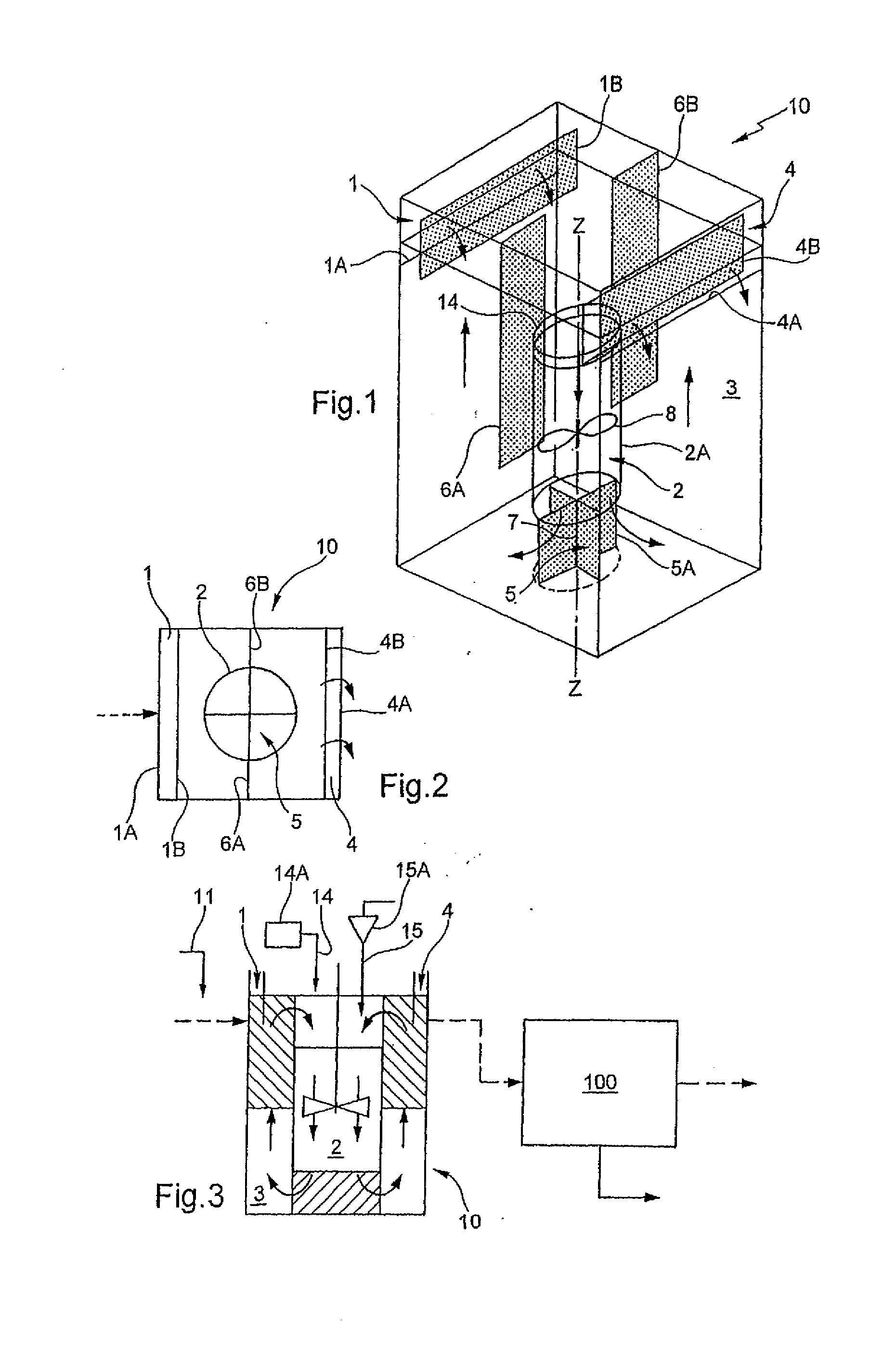
[0091]FIG. 1 is a diagrammatic perspective view of a preferred embodiment of a reactor of the invention,

[0092]FIG. 2 is a diagrammatic plan view of the reactor,

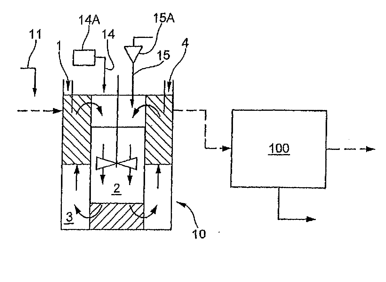
[0093]FIG. 3 is a diagram of a water treatment installation using the reactor shown in FIGS. 1 and 2,

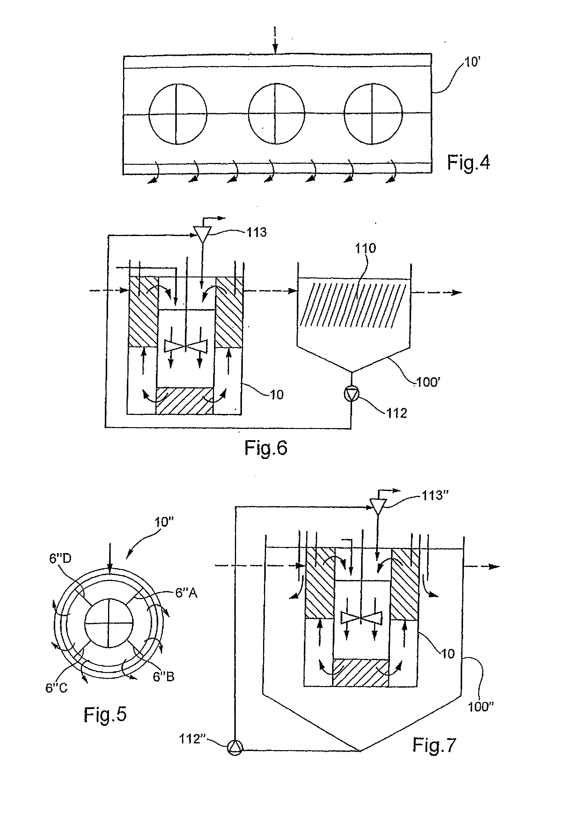
[0094]FIG. 4 is a diagrammatic plan view of a reactor that is a variant of the reactor shown in FIGS. 1 and 2,

[0095]FIG. 5 is a diagrammatic plan view of a reactor that is also a variant of the reactor shown in FIGS. 1 and 2,

[0096]FIG. 6 is a diagram of one variant of the installation shown in FIG. 3, and

[0097]FIG. 7 is a diagram of another variant of the installation shown in FIG. 3.

REACTOR SHAPE

[0098]The reactor 10 shown in FIGS. 1 and 2 is of rectangular shape in order to facilitate connecting a plurality of reactors...


PUM

PropertyMeasurementUnit
particle sizeaaaaaaaaaa
lengthaaaaaaaaaa
diameteraaaaaaaaaa

Abstract

A method and apparatus for treating wastewater. The apparatus comprises a reactor having a flow channel generally centrally located in a reactor and immersed in the water or wastewater in the reactor. An agitator is disposed within the flow channel and induces water or wastewater to enter the open upper end thereof and to move downwardly through the flow channel where the water or wastewater is discharged via a flow divider. A reagent is injected into the water or wastewater and the agitator within the flow channel serves to mix the reagent with the water or wastewater passing therethrough and in the process causes at least a slightly turbulent and downward axial flow through the flow channel.

Description

I—TECHNICAL FIELD OF THE INVENTION[0001]The invention relates to a method and a reactor for the treatment by flocculation of a raw fluid to be treated. The method and the reactor can be used in particular for treating industrial process water, drinking water and municipal or industrial waste water.II—PRIOR ART[0002]Various fluid treatments, in particular in the field of water treatment, involve mixing a raw fluid to be treated with a secondary fluid or flow in order to make the secondary flow react with components of the main fluid; in practice the secondary fluid contains a flocculating agent and it usually contains a granular material on which flocs resulting from the action of the flocculating agent on the impurities of the raw fluid to be treated are formed; this process is known as ballasted floc physical-chemical treatment; the fluids are usually mixed and reacted in full-mixing open reactors equipped with axial-flow vertical-shaft agitators.[0003]In principle a physical-chemi...

Claims


Application Information

Patent Timeline
Patent Type & Authority Applications(United States)
IPC IPC(8): B01D24/44B01D24/48B01D24/40B01D21/00B03D1/16C02F1/00C02F1/24C02F1/52
CPCB01D21/0045B01D21/01B01D21/02B01D21/08B01D21/20B01D21/2405B03D1/1412B03D1/16C02F1/24C02F1/5281C02F2301/024C02F2305/12B01D21/2444B01D21/00
Inventor ESSEMIANI, KARIMURSEL, VALERY
Owner VEOLIA WATER SOLUTIONS & TECH SUPPORT
Why Eureka
Try Eureka