Process and apparatus for treating a workpiece

a technology for treating and workpieces, applied in the direction of lighting and heating apparatus, chemistry apparatus and processes, cleaning using liquids, etc., can solve the problems of high consumption of water, high cost of chemicals, and devices highly susceptible to performance degradation

Inactive Publication Date: 2005-04-07
BERGMAN ERIC J
View PDF69 Cites 9 Cited by
  • Summary
  • Abstract
  • Description
  • Claims
  • Application Information

AI Technical Summary

Benefits of technology

[0013] 1) The use of a temperature controlled liquid chemical source delivered to the wafer surface to stabilize the temperature of the wafer and, depending on the liquid utilized, provide a supply of water to support hydrolysis of the carbon-carbon bonds of contaminants at the surface of each wafer.

Problems solved by technology

This renders the devices highly susceptible to performance degradation due to organic, particulates or metallic / ionic contamination.
While this process has been effective for a number of years, it nevertheless has certain deficiencies.
Such deficiencies include the high cost of chemicals, the lengthy process time required to get wafers through the various cleaning steps, high consumption of water due to the need for extensive rinsing between chemical steps, and high disposal costs.
However, such cleaning processes have failed to fully address all of the major cleaning concerns of the semiconductor processing industry.
More particularly, they have failed to fully address the problem of minimizing contamination from one or more of the following contaminants: organics, particles, metals / ions, and silicon dioxide.

Method used


Image

  • Process and apparatus for treating a workpiece
  • Process and apparatus for treating a workpiece
  • Process and apparatus for treating a workpiece

Examples


Embodiment Construction

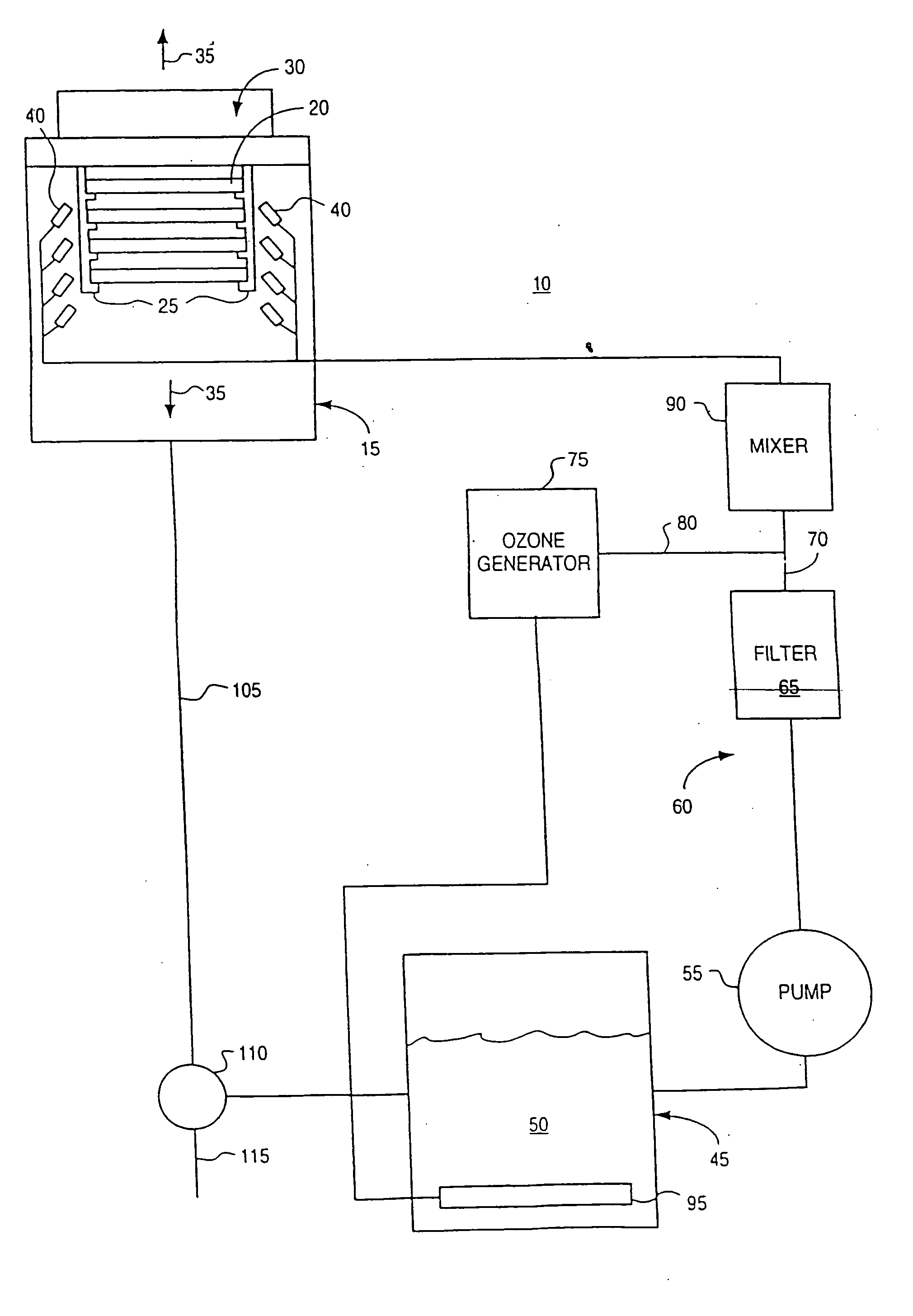
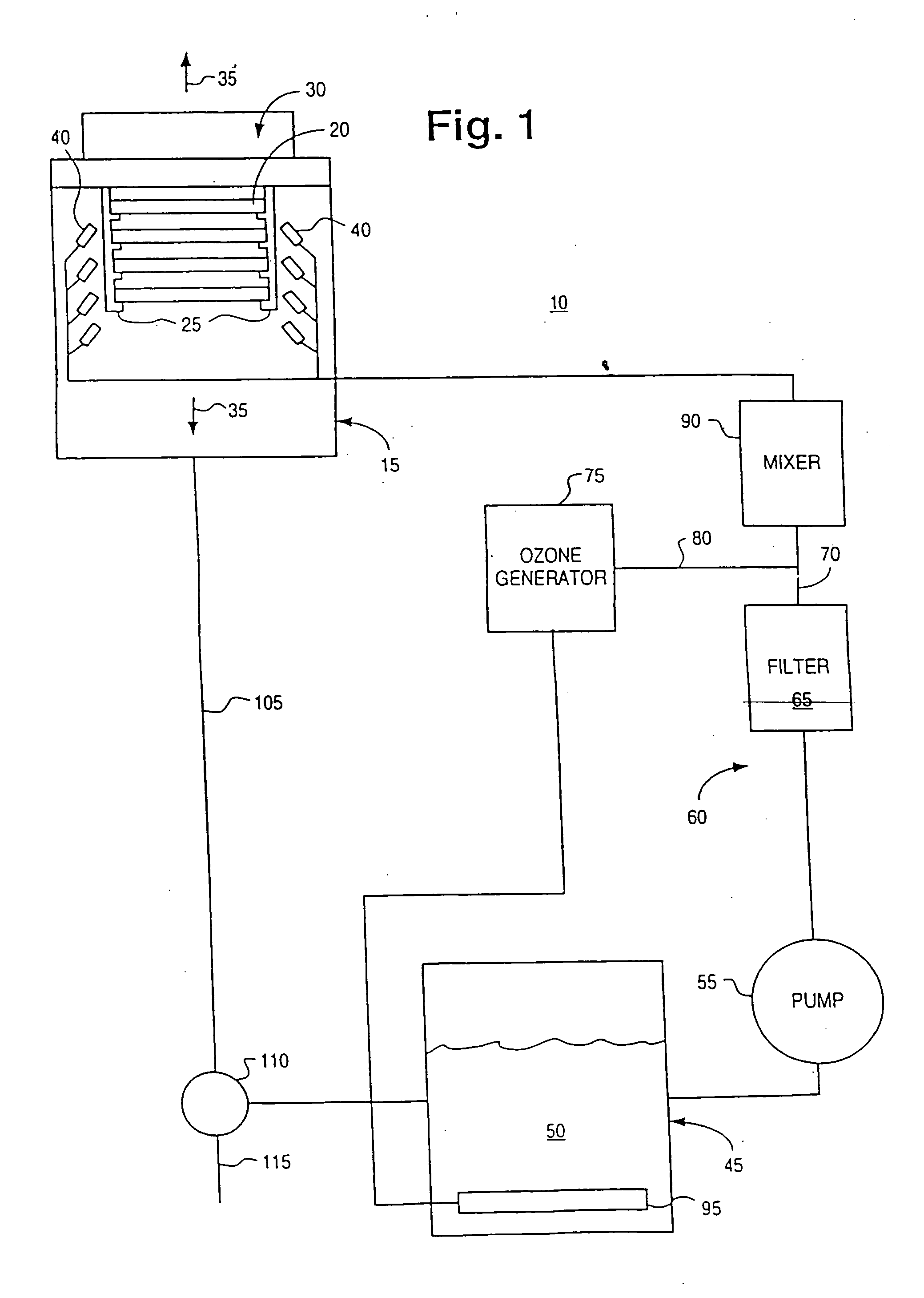
[0023] Referring to FIG. 1, the treatment system, shown generally at 10, includes a treatment chamber 15 that contains one or more workpieces 20, such as semiconductor wafer workpieces. Although the illustrated system is directed to a batch workpiece apparatus, it is readily adaptable for use in single workpiece processing as well.

[0024] The semiconductor workpieces 20 are preferably supported within the chamber 15 by one or more supports 25 extending from, for example, a rotor assembly 30. Rotor assembly 30 may seal with the housing of the treatment chamber 15 to form a sealed, closed processing environment. Further, rotor assembly 30 is provided so that the semiconductor workpieces 20 may be spun about axis 35 during or after treatment with the ozone and treatment liquid.

[0025] The chamber 15 has a volume which is minimized, and is as small as permitted by design considerations for any given capacity (i.e., the number and size of the substrates to be treated). The chamber 15 is ...


PUM

PropertyMeasurementUnit
thicknessaaaaaaaaaa
thicknessesaaaaaaaaaa
temperaturesaaaaaaaaaa

Abstract

A novel chemistry, system and application technique reduces contamination of semiconductor wafers and similar substrates and enhances and expedites processing. A stream of liquid chemical is applied to the workpiece surface. Ozone is delivered either into the liquid process stream or into the process environment. The ozone is preferably generated by a high capacity ozone generator. The chemical stream is provided in the form of a liquid or vapor. A boundary layer of liquid or vapor forms on the workpiece surface. The thickness of the boundary layer is controlled. The chemical stream may include ammonium hydroxide for simultaneous particle and organic removal, another chemical to raise the pH of the solution, or other chemical additives designed to accomplish one or more specific cleaning steps.

Description

[0001] This Application is a Continuation of U.S. patent application Ser. No. 09 / 621,028, filed Jul. 21, 2000 and now pending and incorporated herein by reference, which is a Continuation-in-Part of U.S. patent application Ser. No. PCT / US99 / 08516, which is a Continuation-in-Part of U.S. patent application Ser. No. 09 / 061,318, filed Apr. 16, 1998 and now abandoned, which is a Continuation-in-Part of U.S. patent application Ser. No. 08 / 853,649, filed May 9, 1997, now U.S. Pat. No. 6,240,933. This Application also is a Continuation-in-Part of U.S. patent application Ser. No. 60 / 145,350, filed Jul. 23,1999.FIELD OF THE INVENTION [0002] The cleaning of semiconductor wafers is often a critical step in the fabrication processes used to manufacture integrated circuits or the like. The geometries on wafers are often on the order of fractions of a micron, while the film thicknesses may be on the order of 20 Angstroms. This renders the devices highly susceptible to performance degradation due ...

Claims


Application Information

Patent Timeline
Patent Type & Authority Applications(United States)
IPC IPC(8): B08B3/02B08B3/08B08B7/00H01L21/00H01L21/02H01L21/306
CPCB08B3/02B08B3/08B08B7/00B08B2203/005Y10S134/902H01L21/02052H01L21/02054H01L21/6704B08B2230/01
Inventor BERGMAN, ERIC J.
Owner BERGMAN ERIC J
Why Eureka
Try Eureka