Fluorescent non-metallic particles encapsulated in a metallic coating

a non-metallic particle, fluorescence technology, applied in the field of optical elements, can solve the problems of dramatic increase of losses, failure to fabricate microcavities with sizes below one micron, etc., and achieve the effect of enhancing the total radiative power of such nanocavities, reducing the number of cavity modes, and reducing the number of cavities

Inactive Publication Date: 2009-12-10
FUJIREBIO CO LTD
View PDF4 Cites 33 Cited by
  • Summary
  • Abstract
  • Description
  • Claims
  • Application Information

AI Technical Summary

Benefits of technology

[0079]The present embodiment provides a particle 1 comprising a non-metallic core 2 having a fluorescent material 3 and a metallic shell 4 encapsulating the non-metallic core 2, the use of such a particle 1 in a small scale device as well as a way of fabricating closed metal cavities for the said particle 1, in which optical cavity modes can be excited from the outside without suffering from the high reflection losses for the external pump radiation as usually found in such systems. Therefore, a high population of the cavity modes can be achieved by the present embodiment. Due to the optical properties of the metallic coating 4, the cavities can be scaled down into the sub-micron size regime to form true “nanocavities”. At such small size and high mode population, quantum effects become important in these systems, which are hardly observable in larger cavities with an average size above one micron. First of all, the small particle diameter causes a strong dependence of the position of the cavity modes on molecular adsorption, which can be used for the development of ultimate “single-molecule” nano-biosensors. Second, due to Purcell enhancement of the spontaneous emission rate of the fluorescent material 3 used for mode population inside of the nanocavity, the total radiative power of such nanocavities becomes significantly enhanced (factor of 30 or more), so that the cavity modes can be easily detected despite the small size of the nanocavity and stay well above the noise level. Finally, for very small cavities and very high cavity mode populations, further quantum effects, such as cavity mode splitting become observable. The dependence of this mode splitting on the refractive index in close vicinity of the nanocavity can be used for sensing applications, similar to the tracking of absolute cavity mode positions.
[0080]A cavity with the ability to confine photons, if they match the frequency of a given cavity mode m, can be fabricated in the following way:
[0081]A small non-metallic particle having a fluorescent material 3, such as dye molecules, semiconductor quantum dots, carbon nanotubes, Raman emitters or the like inside or on the surface thereof, is coated with a metallic shell 4, e.g. made from silver (FIG. 3). Here, the metallic shell 4 functions as the “highly reflective closed boundary area” as introduced in the above definition. The fluorescent material 3 inside or on the surface of the core 2 of the particle 1 is excited by means of a pump laser or another strong light source operating at a wavelength that can easily penetrate the metallic coating 4. In the case of a silver shell for example, the wavelength can be chosen to be located around 320 nm, since silver shows maximum transmission around this value. The fluorescent material 3 is chosen such that it emits at a wavelength for which the metallic coating 4 shows high reflectance. Accordingly, the emitted photons are trapped inside of the cavity and the latter confines the photons to a small volume. In accordance with the present embodiment, the following quantum effects will be observable principally in such systems depending on volume and Q-factor, which can all well be utilized for optical sensing on the nanoscale:
[0083]The cavity modes depend on the geometry (volume and shape) of the cavity as well as the reflectance of its surface, which actually defines the Q-factor of the cavity. In the case of photons inside of a spherical metal-coated cavity, the allowed wavelengths of the cavity modes can be described in good approximation by eq. 2. This simplified equation is deduced from the fact that the field intensity has to vanish on the metal coating 4 at any time (FIG. 2). The exact position of the cavity modes depends crucially on the size of the spherical cavity. A simple calculation yields

Problems solved by technology

Summarizing, attempts of fabricating microcavities with sizes below one micron, i.e. “nanocavities”, which might be useful for the development of true nanosensors, have not been successful so far.
(i) Non-metallic cavities without metallic coating, in which only so-called “Whispering Gallery Modes” (WGM) can be excited via total internal reflection, show a dramatic increase of losses with decreasing particle diameter, since the average incidence angle of the light onto the interface between particle and environment becomes smaller and smaller, thereby violating the condition of large incidence angles above the critical angle αcrit.
Therefore, excitation of a fluorescent material embedded inside of a microcavity for population of the cavity modes was not easy to achieve and therefore has not been tried by the others so far.

Method used


Image

  • Fluorescent non-metallic particles encapsulated in a metallic coating
  • Fluorescent non-metallic particles encapsulated in a metallic coating
  • Fluorescent non-metallic particles encapsulated in a metallic coating

Examples


embodiments

Excitation of Optical Cavity Modes in a Surface-Adsorbed Fluorescent Non-Metallic Particle Encapsulated into a Metallic Coating

[0110]Optical cavity modes can be excited and detected in a simple manner according to the schemes shown in FIG. 4.

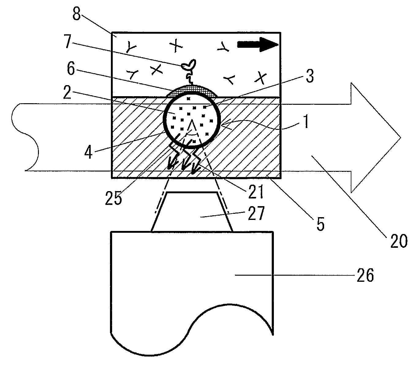
[0111]In the case of scheme (I), the particle 1, consisting of a non-metallic core 2 material containing a fluorescent material 3 and encapsulated into a metallic coating 4 is entirely coated with the metal 4 and adsorbed with the metallic coating 4 in contact with the surface. A light beam 20 used for excitation of the fluorescent material 3 inside of the metallic coating 4 is directed onto the surface, where it is reflected and / or transmitted, depending on the optical properties of the substrate 5. Due to leakage of the cavity, i.e. its finite quality factor, some light 21 of the excited cavity modes is emergent from the particle 1 into its outer environment, where it is collected by suitable optics, e.g. a convex lens 22, and guided to a phot...

example 1

Sensitivity Estimate for Spherical Cavities Based on Quantum Interference Effects

[0145]This example gives an estimate on the expected sensitivity of a single cavity with respect to biomolecular adsorption, if the cavity volume is chosen as small as possible for the wavelength, at which the cavity is operated (according to eq. 5a). We chose realistic materials, which can be purchased, e.g. from Polysciences, Inc. 400 Valley Road, Warrington, Pa. 18976.

[0146]Given:

[0147]1. Polystyrene beads with a refractive index of ncav=1.60 and doped with dye molecules, which emit light at an emission wavelength λem=420 nm

[0148]2. Antibody with a volume of (10 nm)3

[0149]Further assumptions: For calculating a sensitivity estimate, we further assume that

[0150]1. The refractive index of the antibody is larger than that of the surrounding of the cavity, in fact, we assume that it is the same as that of the cavity material. Then, the adsorption of a biomolecule on the outer surface of the cavity causes...

example 2

Estimated Radiative Power of a Single Nanocavity Due to Purcell Enhancement

[0156]Example 1 shows that the sensitivity of a nanocavity with a diameter of 205 nm and operated at a wavelength of 420 nm (emission wavelength of the dye incorporated inside of the cavity) should be high enough for single antibody detection. However, high sensitivity alone does not help for construction of a nano-biosensor if the signal, the sensor radiates, is too weak. Therefore, in this example we give an estimate on the expected radiative power of the system discussed in example 1.

[0157]Further Assumptions:

[0158]1. Dye molecules inside of the cavity have a density of 0.1 / nm3 and a dipole moment typical for organic dyes, d=2×10⁻²⁹ C×m

[0159]2. Further, we assume a Q-factor of Q=100, which in the case of a metal-coated cavity would correspond to a reflectivity of the metallic shell coating 4 of Rsh=97% according to eq. 19 and with all other parameters as given above.

[0160]Estimate:

[0161]Under these assumpt...


PUM

PropertyMeasurementUnit
volumeaaaaaaaaaa
volumeaaaaaaaaaa
volumeaaaaaaaaaa

Abstract

The present invention relates to a particle comprising a non-metallic core having a fluorescent material and a metallic shell encapsulating the non-metallic core wherein the metallic shell has transparency for an electromagnetic radiation having a first wavelength to excite the said fluorescent material and reflectance for an electromagnetic radiation having a second wavelength emitted by the said fluorescent material to confine the electromagnetic radiation having the second wavelength in the metallic shell. This system allows for the excitation of optical cavity modes inside the particle even at sub-micron particle size. The cavity modes are extremely sensitive to any change of the dielectric environment of the particle. This sensitivity can be used for the construction of optical nano-biosensors. Another application of the system is that of a microscopic source for spherical light waves, which may find applications in digital inline holography and display technology.

Description

[0001]This application is a non-provisional application claiming a priority based on a prior U.S. Provisional Application No. 60 / 796,162 filed on May 1, 2006. The entire contents of the Provisional Application No. 60 / 796,162 and another prior U.S. Provisional Application No. 60 / 826,483 filed on Sep. 21, 2006 are incorporated herein by reference.TECHNICAL FIELD[0002]The present invention relates to an optical element comprising fluorescent non-metallic particle(s) with a metallic coating, a method for preparing said particle(s), an optical device comprising said particle(s) and an analytical method using said particle(s) which can be applied to the field of measuring or detecting small amounts of biological or chemical molecules.BACKGROUND ART[0003]Optical microcavities confine light to small volumes by resonant recirculation and have demonstrated potential use as microscopic light emitters, lasers, and sensors (K. J. Vahala, Nature Vol. 424, pp. 839-846, 2004). The recirculation imp...

Claims


Application Information

Patent Timeline
Patent Type & Authority Applications(United States)
IPC IPC(8): G01N21/64
CPCG01N21/6428G01N21/648G01N33/587G01N33/582G01N21/658
Inventor HIMMELHAUS, MICHAEL
Owner FUJIREBIO CO LTD
Why Eureka
Try Eureka