
Mold, process for its production, and process for producing base material having transferred micropattern

a technology of micropatterns and molds, which is applied in the field of molds, process for their production, and process for producing base materials having transferred micropatterns, can solve the problems of low release properties, deterioration of precision of the transferred micropattern of the cured product, and deterioration of the precision of the micropattern of the mold, so as to achieve high mechanical strength, high optical transparency, and high release properties

Inactive Publication Date: 2009-12-10
ASAHI GLASS CO LTD
View PDF1 Cites 10 Cited by
  • Summary
  • Abstract
  • Description
  • Claims
  • Application Information

AI Technical Summary

Benefits of technology

[0014]The present invention provides a mold having high optical transparency, high release properties, high mechanical strength, high dimension stability and a highly precise micropattern, and having less distortion of the micropattern; a production process thereof; and a process for producing a base material with a transferred micropattern capable of transferring a micropattern of the mold with high precision and further having less distortion of the transferred micropattern.Means to Solve the Problems
[0032]The mold of the present invention has high optical transparency, high release properties, high mechanical strength, high dimension stability and a highly precise micropattern, and has less distortion of the micropattern.
[0034]According to the process for producing a base material with a transferred micropattern, it is possible to transfer a micropattern of the mold with good dimensional precision and achieve less distortion of the micropattern.

Problems solved by technology

The mold (1) has low release properties, whereby the precision of the transferred micropattern of the cured product tends to deteriorate at the time of releasing the mold from the cured product.
However, due to irregularities in thickness of the applied release agent, the precision of the micropattern of the mold tends to deteriorate.
Further, when the mold is used continuously, it is necessary to reapply the release agent, and the production efficiency tends to be low.
Though the mold (2) is excellent in the release properties, such a mold is obtained by molding a specific fluoropolymer, whereby the mechanical strength and the dimension stability are inadequate.

Method used


Image

  • Mold, process for its production, and process for producing base material having transferred micropattern
  • Mold, process for its production, and process for producing base material having transferred micropattern
  • Mold, process for its production, and process for producing base material having transferred micropattern

Examples


example 1

Production of Fluoropolymer (P-1)

[0179]Into an autoclave (made of pressure resistant glass), 100 g of a compound (3-3), 0.5 g of methanol and 0.7 g of a compound (4-1) were added, and the compound (3-3) was polymerized by suspension polymerization to obtain a fluoropolymer (P-1). The fluoropolymer (P-1) is a polymer comprising monomer units represented by the following formula (α-1). The intrinsic viscosity of the fluoropolymer (P-1) was 0.34 dL / g. The glass transition temperature of the fluoropolymer (P-1) was 1080° C. The linear expansion coefficient of the fluoropolymer (P-1) was 74 ppm / ° C. The intrinsic viscosity of the fluoropolymer (P-1) was 0.35 dL / g.

CF2═CFOCF2CF2CF═CF2  (3-3),

((CH3)2CHOCOO)2  (4-1).

example 2

Production of a Fluoropolymer (Hereinafter Referred to as a Fluoropolymer (I-1) Comprising Monomer Units Represented by the Above (α-1) and Having —CF3 at its Terminal

[0180]The fluoropolymer (P-1) was put into an autoclave (made of nickel, internal capacity: 1 L) and the interior of the autoclave was flushed three times with nitrogen gas and then evacuated to 4.0 kPa (absolute pressure). Into the autoclave, fluorine gas diluted to 14 vol % with nitrogen gas was introduced to 101.3 kPa, whereupon the internal temperature of the autoclave was maintained to be 230° C. for 6 hours. The content of the autoclave was recovered to obtain the fluoropolymer (I-1). The infrared absorption spectrum of the fluoropolymer (I-1) was measured, whereby no peak attributable to a carboxyl group was confirmed. The fluoropolymer (I-1) was processed into a film having a thickness of 100 μm, and the transmittance of light with wavelengths of from 300 to 500 nm was measured, whereby it was found to be at le...

example 3

Production of Fluoropolymer (Hereinafter Referred to as Fluoropolymer (II-1)) Containing Monomer Units Represented by the Above (α-1) and Having a Reactive Group (y) (Carboxyl Group) at its Terminal

[0182]The fluoropolymer (P-1) was heat-treated at 300° C. for 1 hour in a hot air circulated oven in an atmospheric pressure, then immersed in ultrapure water at 110° C. for 1 week and further dried at 100° C. for 24 hours in a vacuum drier to obtain the fluoropolymer (II-1). The infrared absorption spectrum of the fluoropolymer (II-1) was measured, whereby a peak attributable to a carboxyl group was confirmed at 1,810 cm−1. The polymer (II-1) was processed into a film having a thickness of 100 μm, whereupon the transmittance of light with a wavelength of from 300 to 500 nm was measured, whereby it was found to be at least 93%. The linear expansion coefficient of the fluoropolymer (II-1) was 74 ppm / ° C. The intrinsic viscosity of the fluoropolymer (II-1) was 0.34 dL / g.

Preparation of Solut...


PUM

PropertyMeasurementUnit
temperatureaaaaaaaaaa
thicknessaaaaaaaaaa
thicknessaaaaaaaaaa

Abstract

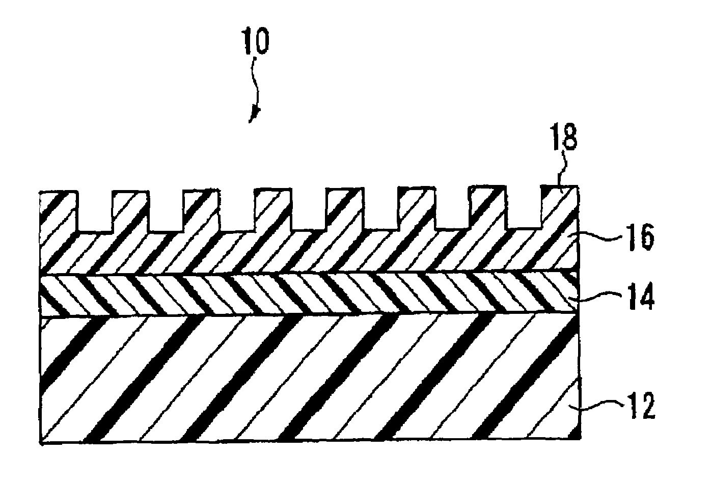
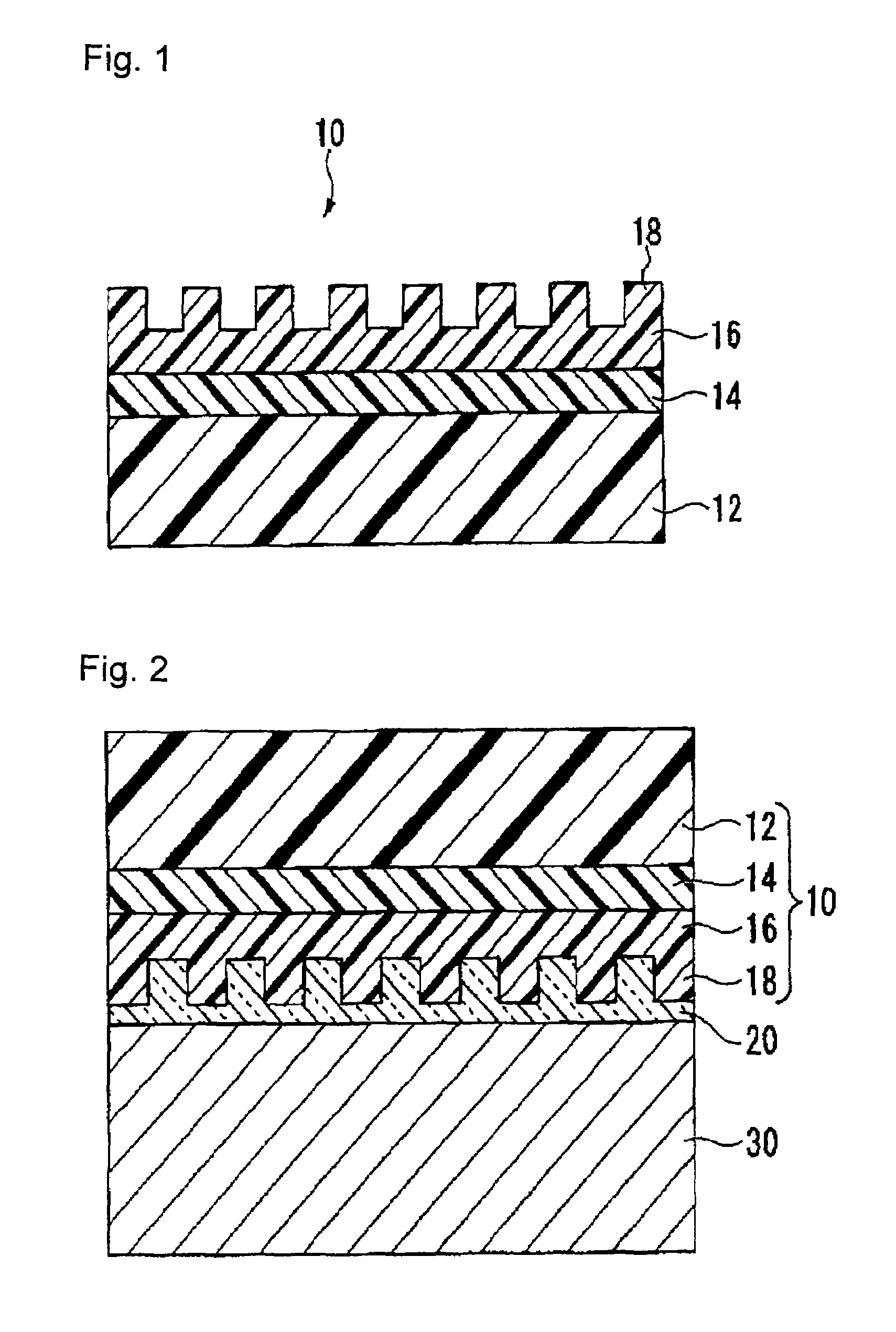
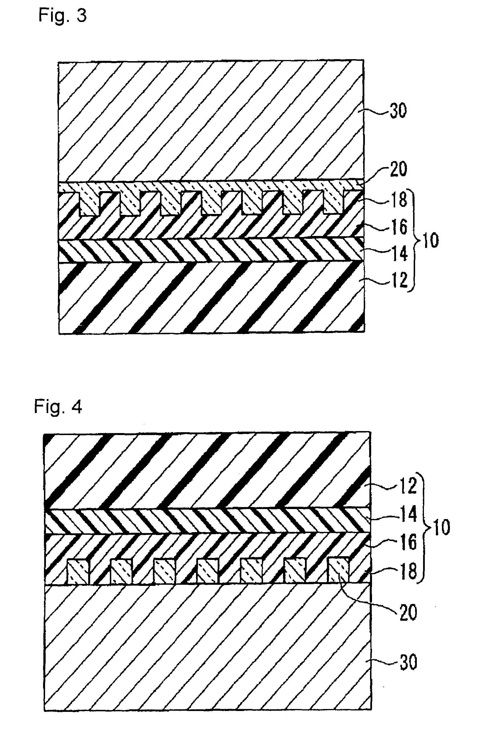
To provide a mold having optical transparency, release properties, mechanical strength, dimension stability and a highly precise micropattern, and having less deformation of the micropattern; and a process for producing a base material with a transferred micropattern having less deformation of the transferred micropattern, capable of transferring highly precise micropattern of the mold.A mold 10 comprising a transparent substrate (A) 12 having chemical bonds based on the functional groups (x) on the surface having an interlayer (C) 14 formed, having a difference in linear expansion coefficient (absolute value) of less than 30 ppm / ° C. from the linear expansion coefficient of the following fluoropolymer (I), and further having a heat distortion temperature of from 100 to 300° C.; an interlayer (C) 14 made of a fluoropolymer (II) having a fluorinated alicyclic structure in its main chain and further having reactive groups (y) reactive with the functional groups (x); and a surface layer (B) 16 having a micropattern on the surface, made of a fluoropolymer (I) having a fluorinated alicyclic structure in its main chain and having substantially no reactive groups (y).

Description

TECHNICAL FIELD[0001]The present invention relates to a mold, a process for its production, and a process for producing a base material having a transferred micropattern, made of a cured product of a photocurable resin, which employs the mold.BACKGROUND ART[0002]In recent years, attention has been drawn to a method, so-called a nano imprint method, wherein a base material is contacted with a mold having a micropattern on its surface to form on the base material surface a reversed pattern of the micropattern (Patent Documents 1 and 2). Particularly, attention has been drawn to a process for producing a base material having a transferred micropattern, which comprises sequentially carrying out a step of interposing a photocurable resin between the micropattern surface of the mold and a base material, a step of irradiating the photocurable resin with light to cure the photocurable resin thereby to form a cure product, and a step of releasing the cured product from the mold.[0003]As the ...

Claims


Application Information

Patent Timeline
Patent Type & Authority Applications(United States)
IPC IPC(8): B29C35/08B28B5/00B29C33/40B81C99/00
CPCB29C33/40B29C33/424B29C33/56B29L2011/00B29C59/005B29C59/02B29C35/0888B29C33/38
Inventor TSUNOZAKI, KENTAROKAWAGUCHI, YASUHIDESAKANE, YOSHIHIKOSHOJI, SHUICHIMIZUNO, JUNKATAZA, SHINGO
Owner ASAHI GLASS CO LTD
Learn More