Implantable materials having engineered surfaces and method of making same

a technology of engineered surfaces and materials, applied in the field of implantable medical devices, can solve the problems of affecting the treatment effect of patients, affecting the treatment effect, so as to improve the loading/delivery capacity of drugs, and promote endothelialization

Active Publication Date: 2009-12-10
VACTRONIX SCI LLC
View PDF64 Cites 27 Cited by
  • Summary
  • Abstract
  • Description
  • Claims
  • Application Information

AI Technical Summary

Benefits of technology

[0007]Provided herein are methods and compositions for implantable materials having engineered surfaces and method of making same. The methods and compositions are set forth in part in the description which follows, and in part will be obvious from the description, or can be learned by practice of the methods, compositions, and systems. In one embodiment, the surface an implantable medical device is chemically etched to provide an engineered surface that promotes endothelialization and improves drug loading / delivery capacity.

Problems solved by technology

However, for grit blasted implants it is known that a risk of remaining particles exists.
Another limitation results from the fact that mechanical stresses are imposed on the material.
When applied to sensitive structures, grit blasting carries the risk of deforming the workpiece.
The technique may be time consuming and very difficult to apply for complex geometries like cardiovascular stents.

Method used


Image

  • Implantable materials having engineered surfaces and method of making same
  • Implantable materials having engineered surfaces and method of making same
  • Implantable materials having engineered surfaces and method of making same

Examples


example i

UV Irradiated Geometric Feature

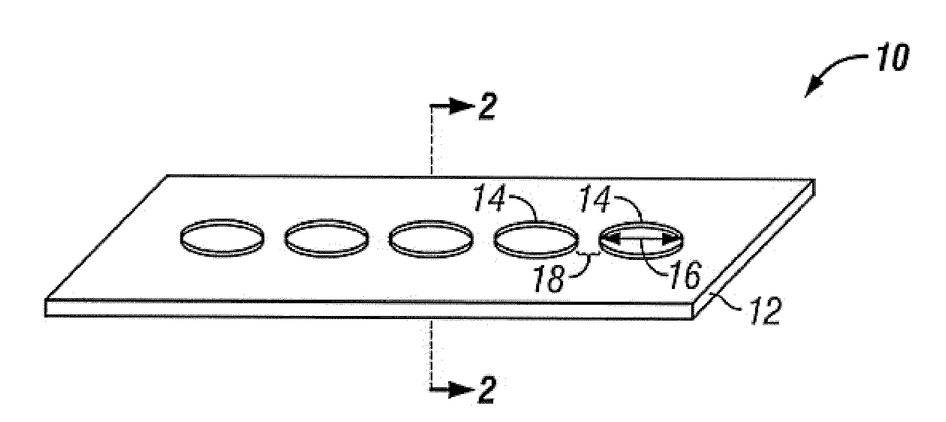
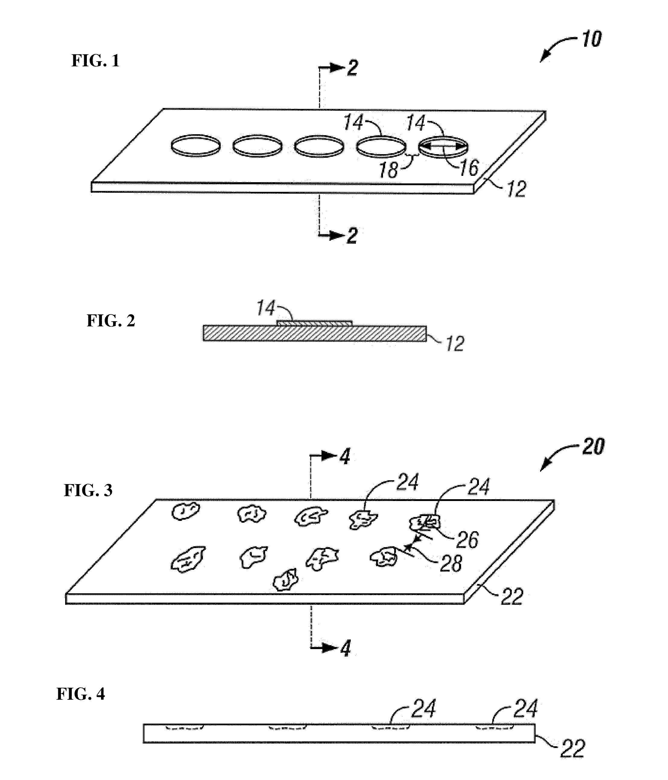
[0100]Nickel-titanium sheets were heated to oxidize titanium present at the surface of the sheet. Pattern masks fabricated from machined metal were laser drilled a pattern of holes having diameters ranging from 15 μm to 50 μm, with a single diameter of holes on each pattern mask. A single pattern mask was placed over a single nickel-titanium sheet and the assembly was exposed to high intensity ultra-violet irradiation. After UV irradiation, the irradiated nickel-titanium sheet was placed on a fully endothelialized test surface and maintained at 37° C. under simulated in vivo flow conditions and under static flow conditions. Qualitative observations were periodically made and it was found that endothelial cells bound to the pattern of UV irradiated affinity domains and migrated across the nickel-titanium sheet by proliferating across the pattern of affinity domains, eventually fully forming an endothelium on the nickel-titanium sheet.

example ii

Geometric Feature CE Surface Microstructure for Enhanced Endothelialization

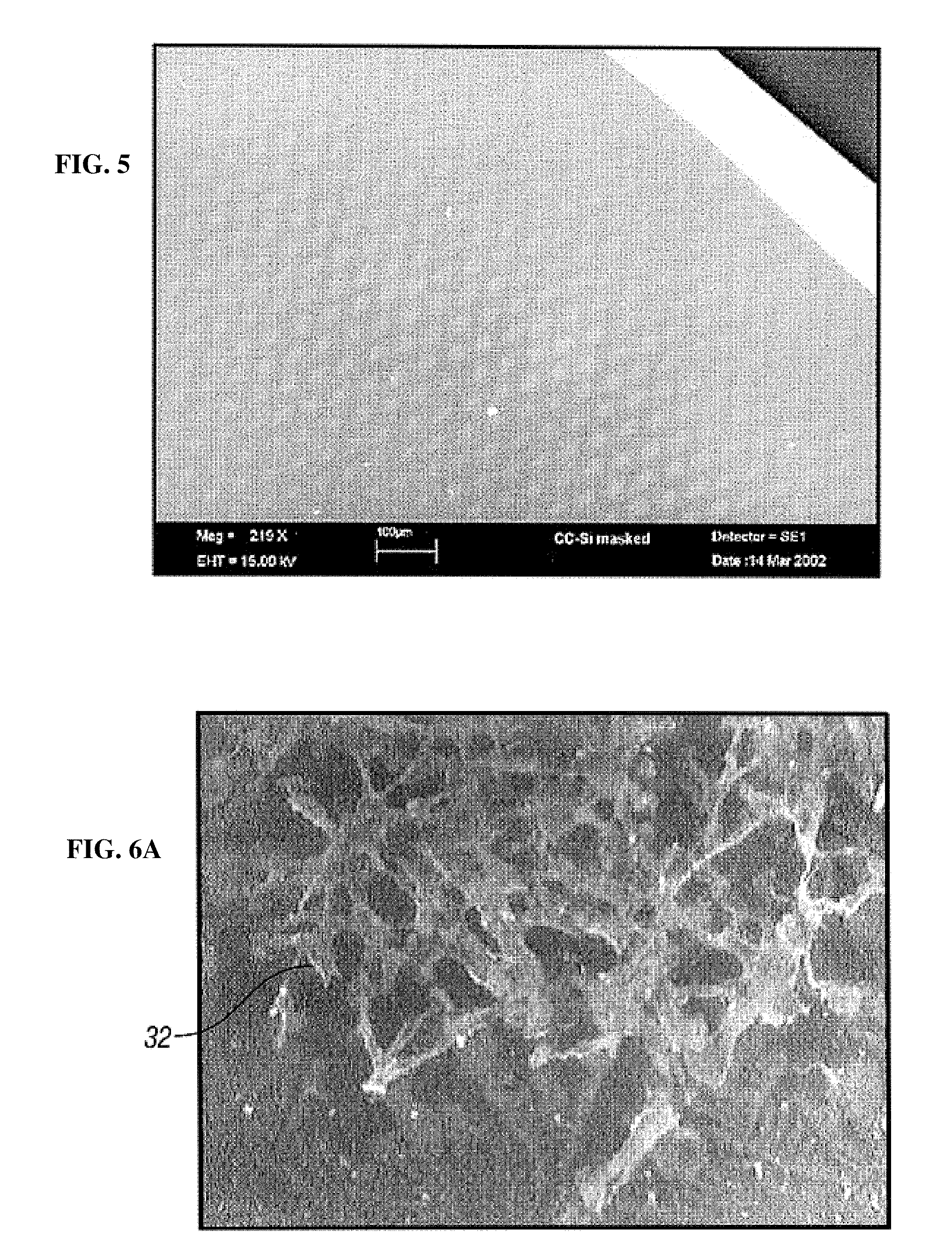
[0101]In an alternative embodiment, the geometric features may be formed by a microstructuring method comprising chemical etching of a biocompatible metal to form a pattern of geometric features 14 on the at least one surface 12 of the biocompatible metal, as shown in FIG. 18. The microstructuring method may be used in the manufacturing of implantable medical devices 10 such as stents, stent-grafts, grafts, valves, shunts and patches, as a method for increasing endothelialization and creating a release system 200 without the use of protective polymers. The geometric features 14 create a charge difference on the surface 12 leading to a chemical heterogeneity. The geometric features 14 may comprise a chemically etched (CE) surface including a grain structure 100 and a plurality of grain boundaries 140 including a positively charged characteristic as compared to the grain structure 100. The geometric features in...

example iii

Grain Size of the CE Surface for Endothelial Attachment

[0120]In another embodiment, the geometric feature 12 comprises the CE surface 110 including a smooth grain surface 120. The smooth grain surface 120 includes a grain size 122, a plurality of grain boundaries 140 (GB) surrounding the grain feature, as shown in FIG. 20C. The grain boundary 140 is the dividing surface between two adjacent grain crystals having a different crystallographic orientation. The grain feature 120 and the grain boundaries 140 are three dimensional. The grain boundary includes an abrupt orientation change, occurring over only one or two atomic planes. Because of this, the grain boundary includes atoms that are displaced out of their lattice positions to positions of a lowest energy due to a lattice misfit where the crystals meet. Hence, an increased energy above the normal lattice energy is associated with the displaced atoms at the grain boundary, giving rise to a localized grain boundary energy. When the...


PUM

PropertyMeasurementUnit
roughnessaaaaaaaaaa
water contact angleaaaaaaaaaa
roughnessaaaaaaaaaa

Abstract

Implantable materials having engineered surfaces and method of making same comprising geometric features on at least one surface of the material having at least one of chemical, physiochemical and electrochemical activity different than regions of the at least one surface without the features.

Description

CROSS-RELATED APPLICATIONS[0001]This application is a continuation-in-part and claims priority to U.S. patent application Ser. No. 11 / 091,669, filed Mar. 28, 2005, which claims priority to PCT International Application No. PCT / US03 / 030383, filed Sep. 26, 2003, which claims priority to U.S. Provisional Application Ser. No. 60 / 414,031, filed Sep. 26, 2002, all of which are incorporated by reference herein.BACKGROUND OF THE INVENTION[0002]The present invention relates generally to implantable medical devices and more particularly to controlling surface properties of implantable biocompatible materials suitable for fabrication of implantable medical devices.[0003]Various materials have been used for the purpose of substituting or supporting organic functions of the human body, ranging from metals to ceramics to polymers. Almost all materials currently used are still being optimized in terms of composition and processing. In recent times, the focus has been aiming more and more toward th...

Claims


Application Information

Patent Timeline
Patent Type & Authority Applications(United States)
IPC IPC(8): A61F2/00
CPCA61F2/0077A61F2/91A61F2/02C23F1/28
Inventor CHOUBEY, ANIMESHPALMAZ, JULIO C.
Owner VACTRONIX SCI LLC
Why Eureka
Try Eureka