Pressure sensor

a pressure sensor and sensor technology, applied in the field of pressure sensors, can solve the problems of thermal distortion of the elements, disadvantageous degradation of the characteristics of the pressure sensor, and error of a measured pressure value, and achieve the effects of reducing the number of steps, low cost and high yield

Inactive Publication Date: 2009-12-17
SEIKO EPSON CORP
View PDF12 Cites 11 Cited by
  • Summary
  • Abstract
  • Description
  • Claims
  • Application Information

AI Technical Summary

Benefits of technology

[0029]An advantage of the invention is to provide a pressure sensor that uses no oil serving as a pressure receiving medium, is manufactured into a small size with fewer steps and with high yield, and is difficult to deteriorate with time and highly sensitive.
[0030]A pressure sensor according to a first aspect of the invention includes: a housing; a pressure input orifice opened at a pipe sleeve of the housing; a diaphragm sealing the pressure input orifice, the diaphragm having a first surface serving as a pressure receiving surface; a pressure sensitive unit using a direction of detecting a force as a detecting axis. A first end of the pressure sensitive unit is connected to a central area of a second surface of the diaphragm. A second end of the pressure sensitive unit is connected to the housing. The detecting axis is approximately orthogonal to the pressure receiving surface. A circumference of a portion where the central area and the first end of the pressure sensitive unit are in contact with each other is located inside a circumference of the central area. A thickness of the central area is larger than a thickness of an area surrounding the central area.
[0031]The above-mentioned configuration does not include oil as an element. Therefore, a problem such as oil leakage as described above does not occur. Also, the diaphragm gives a force to the pressure sensitive unit only in the direction of the detecting axis of the pressure sensitive unit, so the sensitivity of the pressure sensor is improved. Also, stress is concentrated not only on the circumference of the portion where the pressure sensitive unit and central area are connected but also on the circumference of the central area, so the concentration of the stress on the portion where the diaphragm and pressure sensitive unit are connected is reduced. Thus, the stress is reliably is transmitted to the pressure sensitive unit. This improves the sensitivity of the diaphragm, as well as reduces aged deterioration due to repeated concentration of stress. Also, the area surrounding the central area is thin and thus highly bendable, so a reduction in sensitivity caused by a reduction in bendability of the whole diaphragm is prevented.
[0032]In the pressure sensor according to the first aspect of the invention, the surrounding area preferably has a flat surface and there is preferably a step between the surrounding area and the central area.
[0033]Use of the above-mentioned configuration simplifies the manufacture of the diaphragm. Also, the distortion of the central area is reduced, so the concentration of the stress on the portion where the central area and pressure sensitive unit are connected is avoided. As a result, the detecting accuracy is improved.
[0034]In the pressure sensor according to the first aspect of the invention, the pressure sensitive unit preferably includes a force transmitting unit having a first end in contact with a central area of the second surface of the diaphragm, a movable unit fixed to the force transmitting unit, and a pressure sensitive element having a first end in contact with the fixing unit and a second end connected to the housing.

Problems solved by technology

Therefore, when the temperature changes, thermal distortions occur in the elements constituting the pressure sensor 501.
Such thermal distortions act on the double-ended tuning fork resonator 509 as unwanted stress, resulting in an error of a measured pressure value.
Thus, the characteristics of the pressure sensor are disadvantageously degraded.
Thus, an error may occur in a measured pressure value.
Therefore, disadvantageously, the related-art pressure sensor using the oil 510 cannot be used to measure the pressure of a pure liquid into which no foreign substance must be mixed.
This is an obstacle to downsizing the pressure sensor.
This disadvantageously makes the force transmitting unit 505 a costly component, thereby increasing the manufacturing cost of the pressure sensor.
In this case, bubbles may occur in the oil.
If bubbles occur in the oil, the oil serving as a pressure transmitting medium can no longer stably transmit a force to the double-ended tuning fork resonator via the pedestal.
This disadvantageously results in an error of the measured pressure value.
As a result, the pressure detecting sensitivity may be deteriorated.
Thus, the pressure detecting sensitivity is disadvantageously deteriorated.
This disadvantageously deteriorates the pressure detecting sensitivity.
If the diaphragm and center shaft are rigidly fixed in the pressure sensor that is used under high temperature and high pressure, the mechanism may be broken due to the difference in thermal expansion between these elements.
Therefore, there is a very high possibility that when the diaphragm and center shaft operate due to a variation in the pressure, the contact point is misaligned.
If the contact point is misaligned, a force acting on both the diaphragm and center shaft leaks out.
This disadvantageously prevents the pressure sensor from detecting the pressure with high accuracy.
Therefore, it is not preferable to apply these pressure sensors to technologies for downsizing.
This is a major disadvantage in that the measuring accuracy cannot be increased.
As for the diaphragm described in JP-A-08-159900, the central area of the pressure receiving surface is thin; therefore, when an external force such as pressure is applied to the central area, the central area is easily damaged.
The related-art example described in JP-A-2007-132697 does not have the problems that the above-mentioned JP-A-56-119519, JP-A-64-9331, and JP-A-02-228534 have; however, it has, for example, a problem that the material of the diaphragm is limited only to metal such as stainless steel and a problem that such a material is not suited to downsizing, since the diaphragm is formed by means of stamping.
Also, the waveform diaphragm formed by means of stamping, disclosed in JP-A-2007-132697, disadvantageously requires a process of eliminating residual stress applied to the diaphragm during stamping, as a post process.
Further, if, in JP-A-2007-132697, an attempt is made to manufacture a diaphragm using the photolithography technique and etching technique (hereafter collectively referred to as “photolitho-etching”) described in JP-A-08-159900, the front surface and back surface of the diaphragm are apt to be misaligned and therefore it is difficult to perform photolitho-etching with high yield, since both the diaphragms described in JP-A-2007-132697 and JP-A-08-159900 have a complicated structure.
Thus, aged deterioration is disadvantageously apt to occur.
Also, the structures shown in FIGS. 2 to 6 thereof have a problem that a protection member serving as a heat shield plate must be provided on the pressure receiving surface of the diaphragm and thus the manufacturing process is complicated.

Method used


Image

  • Pressure sensor
  • Pressure sensor
  • Pressure sensor

Examples


first embodiment

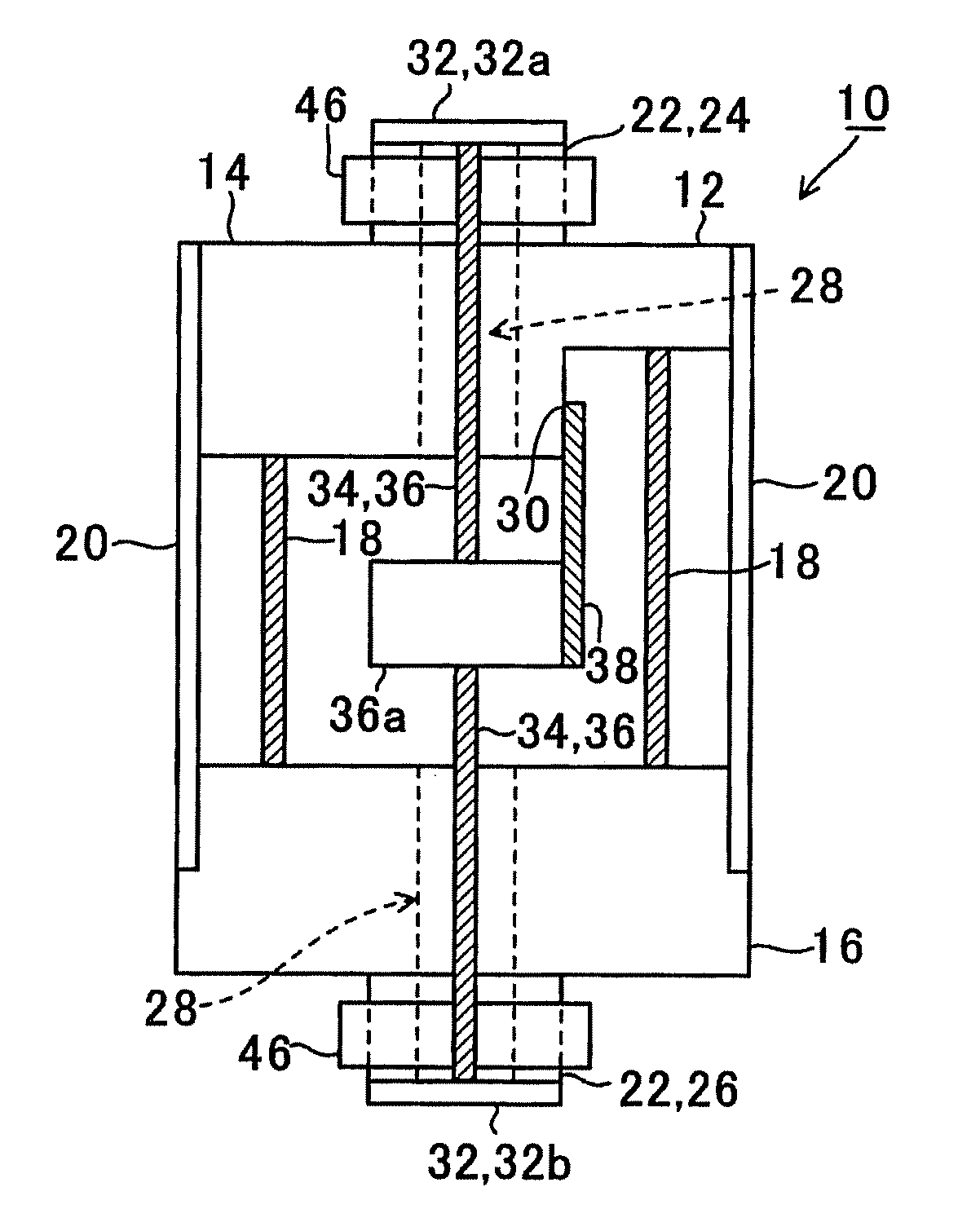
[0105]As is understood from the above description, the pressure sensor does not use oil as an element. Therefore, a problem such as oil leakage does not occur. Also, the force transmitting unit 34 transmits a force only in the direction of the end surfaces of the pressure sensitive element 38, so the sensitivity of the pressure sensor 10 is improved. Also, stress is concentrated not only on a circumference 401 of the portion where the force transmitting unit 34 and center area 40 make contact with each other but also on a circumference 421 of the center area 40, that is, the boundary between the center area 40 and thin portion 42. Thus, the concentration of stress on the portion where the diaphragm 32 and force transmitting unit 34 make contact with each other is reduced and the stress is reliably transmitted to the force transmitting unit 34. As a result, the sensitivity of the pressure sensor 10 is improved. Also, aged deterioration due to repeated stress concentration is reduced...

fourth embodiment

[0118]In the fourth embodiment, the hermetic terminal board 114 is used as the upper end face plate and a hermetic terminal 160 is passed through the hermetic terminal board 114 so that a signal generated by the pressure sensitive element 138 is taken out.

[0119]By adopting the fourth embodiment having such a configuration, the pair of diaphragms 132 are coupled via the center shaft 136, and the movable unit 157 provided on the intermediate portion of the center shaft 136 moves (this movement is a movement attributable to the difference between the pressures received by the pair of diaphragms 132A and 132B) in the shaft axis direction in accordance with the movement of the diaphragms 132, together with the center shaft 136. This movement generates an acting force of the pressure sensitive element138, which is a double-sided fork tune resonator, in the detecting axis direction. As a result, there is formed a pressure sensor that uses no oil and has high detecting accuracy and that is ...

fifth embodiment

[0124]In the pressure sensor 200 the circumferential groove 242 is dug into both surfaces of an area surrounding a center area 240 of each diaphragm 232, and the center area 240 and a peripheral area 244 are thick portions and the portion on which the circumferential groove 242 is made is relatively thin. Therefore, if each diaphragm 232 receives pressure and thus becomes distorted, the flatness of the center area 240 thereof is maintained. Thus, a force in the axis direction is more accurately transmitted to the center shaft 136 connected to the center area 240. As a result, the detecting accuracy is improved. In particular, the front surface and back surface of each diaphragm 232 are symmetrical, so the diaphragms 232 are very easy to assemble as components.

[0125]FIG. 11 shows a sectional view of a pressure sensor 300 according to a sixth embodiment of the invention. In an example shown in the drawing, there is shown a pressure sensor that is intended to detect an absolute pressu...


PUM

PropertyMeasurementUnit
thicknessesaaaaaaaaaa

Abstract

A pressure sensor includes: a housing; a pressure input orifice opened at a pipe sleeve of the housing; a diaphragm sealing the pressure input orifice, the diaphragm having a first surface serving as a pressure receiving surface; a pressure sensitive unit using a direction of detecting a force as a detecting axis. A first end of the pressure sensitive unit is connected to a central area of a second surface of the diaphragm. A second end of the pressure sensitive unit is connected to the housing. The detecting axis is approximately orthogonal to the pressure receiving surface. A circumference of a portion where the central area and the first end of the pressure sensitive unit are in contact with each other is located inside a circumference of the central area. A thickness of the central area is larger than a thickness of an area surrounding the central area.

Description

BACKGROUND[0001]1. Technical Field[0002]The present invention relates to a pressure sensor, in particular, a pressure sensor that does not use oil as a pressure receiving medium.[0003]2. Related Art[0004]There have been known pressure sensors using a piezoelectric resonator as a pressure sensitive element, such as a water pressure gauge, an air gauge, and a differential pressure gauge. For example, in a piezoelectric resonator, an electrode pattern is formed on a planar piezoelectric substrate, and a detecting axis is set in the direction of detecting a force. When pressure is applied to the piezoelectric resonator in the direction of the detecting axis, the resonance frequency of the piezoelectric resonator varies. The pressure is detected on the basis of the variation in the resonance frequency. JP-A-56-119519, JP-A-64-9331, and JP-A-2-228534 disclose pressure sensors using a piezoelectric resonator as a pressure sensitive element. When pressure is applied to a bellows via a press...

Claims


Application Information

Patent Timeline
Patent Type & Authority Applications(United States)
IPC IPC(8): G01L9/08
CPCG01L9/0022G01L9/0008
Inventor MOTOYAMA, HISAO
Owner SEIKO EPSON CORP
Why Eureka
Try Eureka