Method of coating inner and outer surfaces of pipes for thermal solar and other applications

a technology of thermal solar and other applications, applied in the direction of coatings, plasma techniques, lighting and heating apparatus, etc., can solve the problems of poor quality coating, etc., and achieve the effects of improving ionization rates, poor quality, and adverse effects on the quality of the coating

Active Publication Date: 2009-12-17
AGM CONTAINER CONTROLS
View PDF12 Cites 22 Cited by
  • Summary
  • Abstract
  • Description
  • Claims
  • Application Information

AI Technical Summary

Benefits of technology

[0005]A method in accordance with the present invention enables coating of an exterior surface of a workpiece, such that the coating exhibits desired (target) coating properties. In some applications, the exterior surfaces of a number of workpieces are coated simultaneously, such as in the coating of piston rings or similar workpieces. As a first step, a chamber having a multi-dimensional interior surface is provided. The multi-dimensional interior surface has a particular geometry with respect to an axis of the chamber. For example, the chamber may be cylindrical. Each workpiece is positioned within the chamber so that the spacing between the multi-dimensional interior surface and the exterior surface of the workpiece remains substantially fixed along the axial direction of the chamber. Where the workpiece is cylindrical, the workpiece is positioned coaxially within the cylindrical chamber. Conditions are established to maintain a hollow cathode effect within the spacing between the interior surface of the chamber and the exterior surface of the workpiece, thereby defining a hollow cathode effect region. The interior surface of the chamber and the exterior surface of the workpiece are biased as cathodes, but not necessarily at the same biased voltage, while anodes are located at opposite ends of the hollow cathode effect region.
[0006]As defined herein, the “hollow cathode effect” occurs when at least two cathode surfaces are positioned opposite to each other and are electrically cooperative with spaced apart anodes, such that an “oscillation motion” of electrons is achieved to increase ionization rates within a plasma. The spacing between the inner chamber wall and the exterior surface of the workpiece is selected so as to control the plasma intensity, as well as plasma focusing. If this spacing is below a desired range, the intense plasma will be too close of the surface being coated, causing intense ion bombardment and heating, so that the quality of the coating will be adversely affected. On the other hand, if the spacing is above the target range, the bias voltages for achieving the hollow cathode effect will need to be high, thereby causing thermal spikes that may result in a poor quality coating. In one embodiment, the desired coating is a diamond-like coating (DLC). Another consideration is the aspect ratio of the length of the hollow cathode effect region to the distance across the hollow cathode effect region. As the length between one of the anodes and the most distance part of the workpiece increases (typically the distance to the center of the workpiece), the distance that an electron must travel increases. The uniformity of the coating thickness is promoted by maintaining this aspect ratio within a given limit, such below the aspect ratio of 50:1.
[0007]Particularly if the method is implemented to simultaneously coat a number of workpieces, the workpieces may be supported along a rod that is coaxial with the chamber. However, the method may also be used in simultaneously coating exterior and interior surfaces of a workpiece, such as a tube. Thus, the hollow cathode effect may be established within the tube, as well as within the spacing between the tube and the chamber wall. The coating applied to the interior of the tube may be the same as the coating applied to the exterior or may be different either with respect to coating properties (e.g., thickness) or coating materials.
[0008]A system in accordance with the invention may include a large diameter tube that functions as the chamber. A small diameter member is then located coaxially within the large diameter tube, such that the hollow cathode effect region is defined between the small diameter member and the large diameter tube. Anodes are located at opposite sides of this region and a biasing system is connected to bias the anodes and to establish the large diameter tube and the small diameter member as cathodes. A gas supply is connected to provide a flow of reactant gas within the hollow cathode effect region at a pressure that is cooperative with the biasing system to establish the hollow cathode effect.

Problems solved by technology

If this spacing is below a desired range, the intense plasma will be too close of the surface being coated, causing intense ion bombardment and heating, so that the quality of the coating will be adversely affected.
On the other hand, if the spacing is above the target range, the bias voltages for achieving the hollow cathode effect will need to be high, thereby causing thermal spikes that may result in a poor quality coating.

Method used


Image

  • Method of coating inner and outer surfaces of pipes for thermal solar and other applications
  • Method of coating inner and outer surfaces of pipes for thermal solar and other applications

Examples


Embodiment Construction

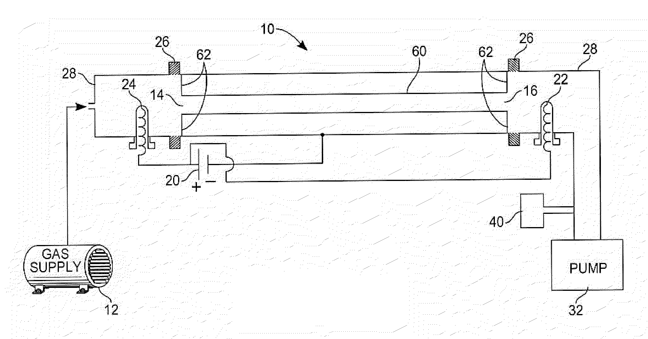
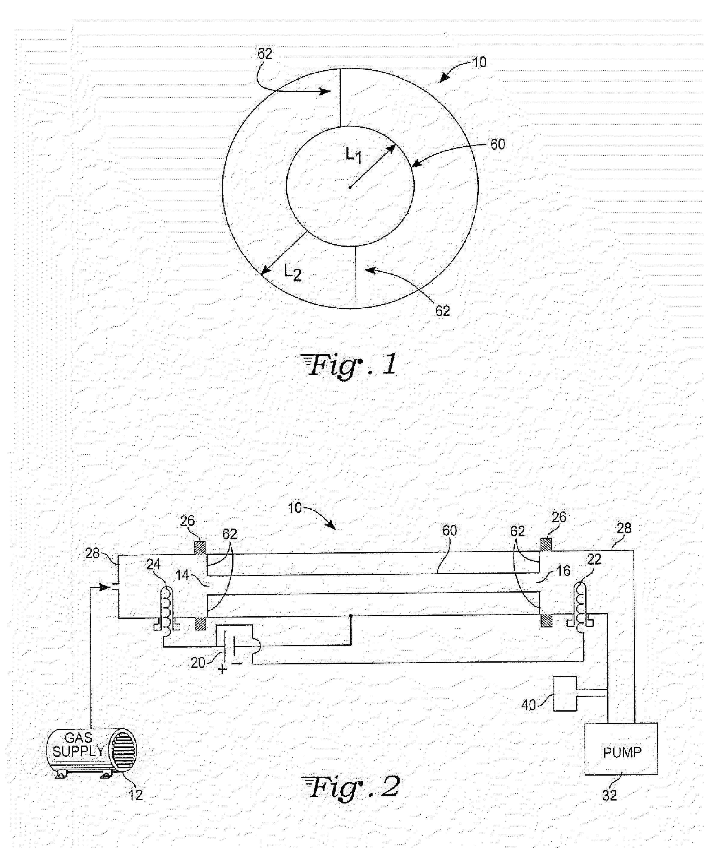
[0011]Referencing FIGS. 1 and 2, a voltage biasing system 20 is connected such that the pipes 10 and 60 (or other hollow workpieces) are biased as cathodes with an anode(s) 24 and / or 22 coupled to at least one opening of each pipe. The inner pipe 60 is electrically connected to the outer pipe 10 through at least one electrical connector 62. A source gas is introduced from a gas subsystem 12 that is coupled to at least one opening of the pipe, and gas is exhausted through a pumping subsystem 32 connected to at least one opening of the pipe.

[0012]In the illustrated application, three surfaces are coated simultaneously. Specifically, the interior and exterior surfaces of the inner pipe 60 and the interior surface of the outer pipe 10 are coated. In other applications, the outer pipe merely functions as a chamber for coating the inner pipe, so that only one workpiece is significant. As another possibility, the interior surface of the inner pipe is not coated. In fact, the inner pipe may...


PUM

PropertyMeasurementUnit
deposition rateaaaaaaaaaa
pressureaaaaaaaaaa

Abstract

In accordance with one embodiment of the invention, a workpiece having a smaller cross sectional dimension (e.g., diameter) is centered within a workpiece having a larger cross sectional dimension, with the workpieces being electrically connected. In this embodiment, surfaces of the two workpieces can be coated simultaneously, either with the same coating material or different coating materials. In another embodiment, holes are located along the length of an internal metal tube which functions as a gas distribution injector and anode holder. A ceramic liner may be placed inside the internal metal tube, with a conductive wire within the ceramic liner. The internal metal tube may be biased as a cathode, while the internal wire is biased as an anode. The hollow cathode effect is applied in all spaces directly adjacent to the surface or surfaces being coated. In some applications, different surfaces being coated are biased at different voltages.

Description

CROSS-REFERENCE TO RELATED APPLICATION[0001]This application claims priority from provisional application Ser. No. 61 / 127,432, filed May 13, 2008.TECHNICAL FIELD[0002]This invention describes a method of simultaneously and uniformly coating two internal surfaces and one external surface using high deposition rate hollow cathode techniques. Additionally, the technique teaches a new method for coating the inner and outer surface of a hollow part with two different types of coatings simultaneously.BACKGROUND ART[0003]Plasma Enhanced Chemical Vapor Deposition (PECVD) methods of coating external surfaces of a workpiece within a vacuum chamber are well known. The coating of internal surfaces of hollow workpieces using PECVD technique is less common but has been described in U.S. Pat. No. 7,300,684 to Boardman et al., which utilizes a high deposition rate PECVD technique. The Boardman et al. patent is incorporated herein by reference. The method involves using the pipe itself as a vacuum c...

Claims


Application Information

Patent Timeline
Patent Type & Authority Applications(United States)
IPC IPC(8): C23C16/448F24S10/70
CPCC23C16/045C23C16/503H01J37/32706H01J37/32009H01J37/32596C23C16/515
Inventor BOARDMAN, WILLIAM J.CASSERLY, THOMAS B.UPADHYAYA, DEEPAKBOINAPPALY, KARTHIKRAMAMURTI, RAHUL
Owner AGM CONTAINER CONTROLS
Why Eureka
Try Eureka