
Micro refinery for ethanol production

a micro-refinery and ethanol technology, applied in the direction of specific use bioreactors/fermenters, apparatus sterilization, after-treatment of biomass, etc., can solve the problem of large-scale machinery used in production, and achieve the effect of reducing clogging problems, optimum efficiency, and optimizing distillation performan

Inactive Publication Date: 2009-12-17
E FUEL CORP
View PDF5 Cites 10 Cited by
  • Summary
  • Abstract
  • Description
  • Claims
  • Application Information

AI Technical Summary

Benefits of technology

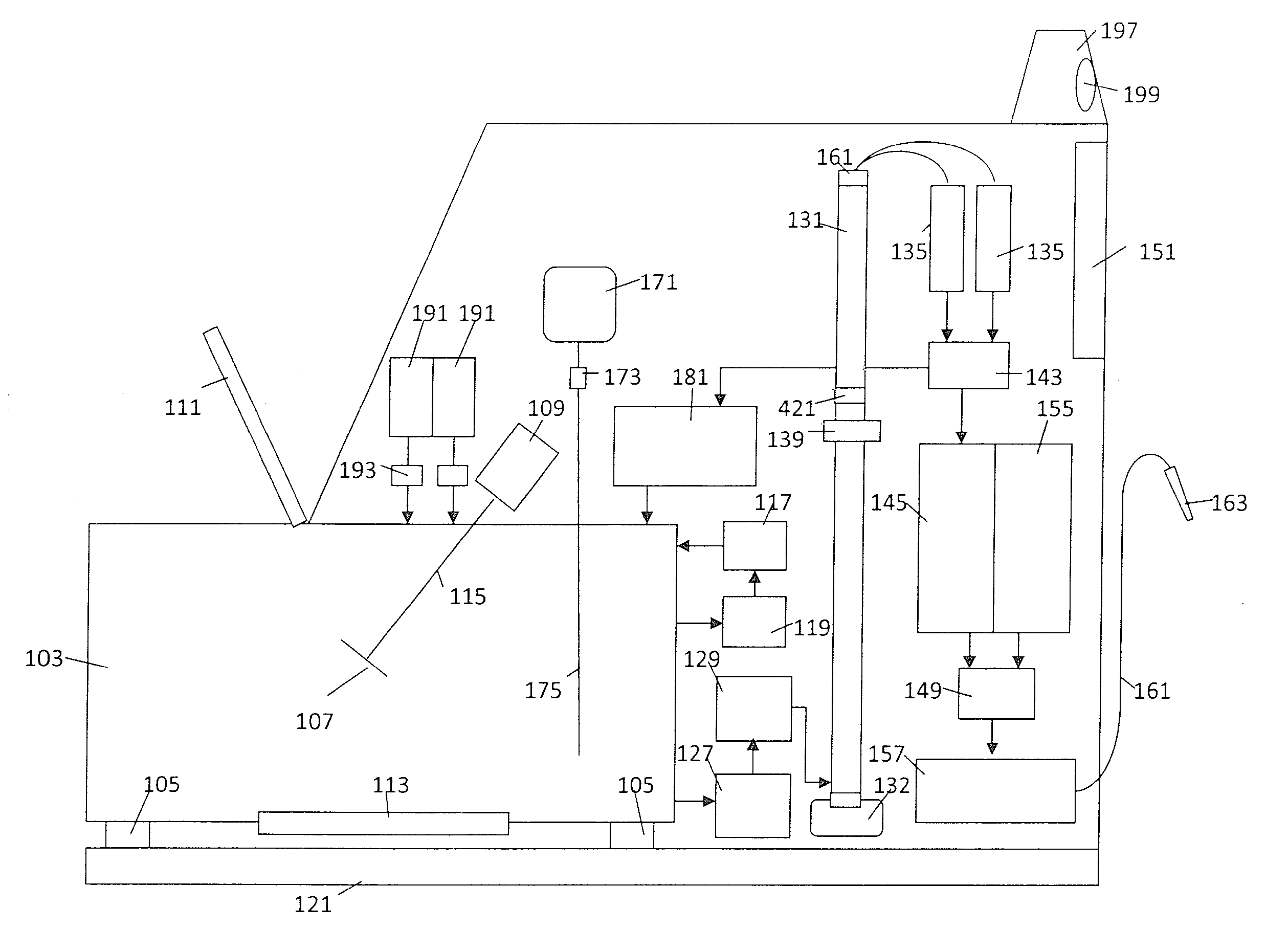
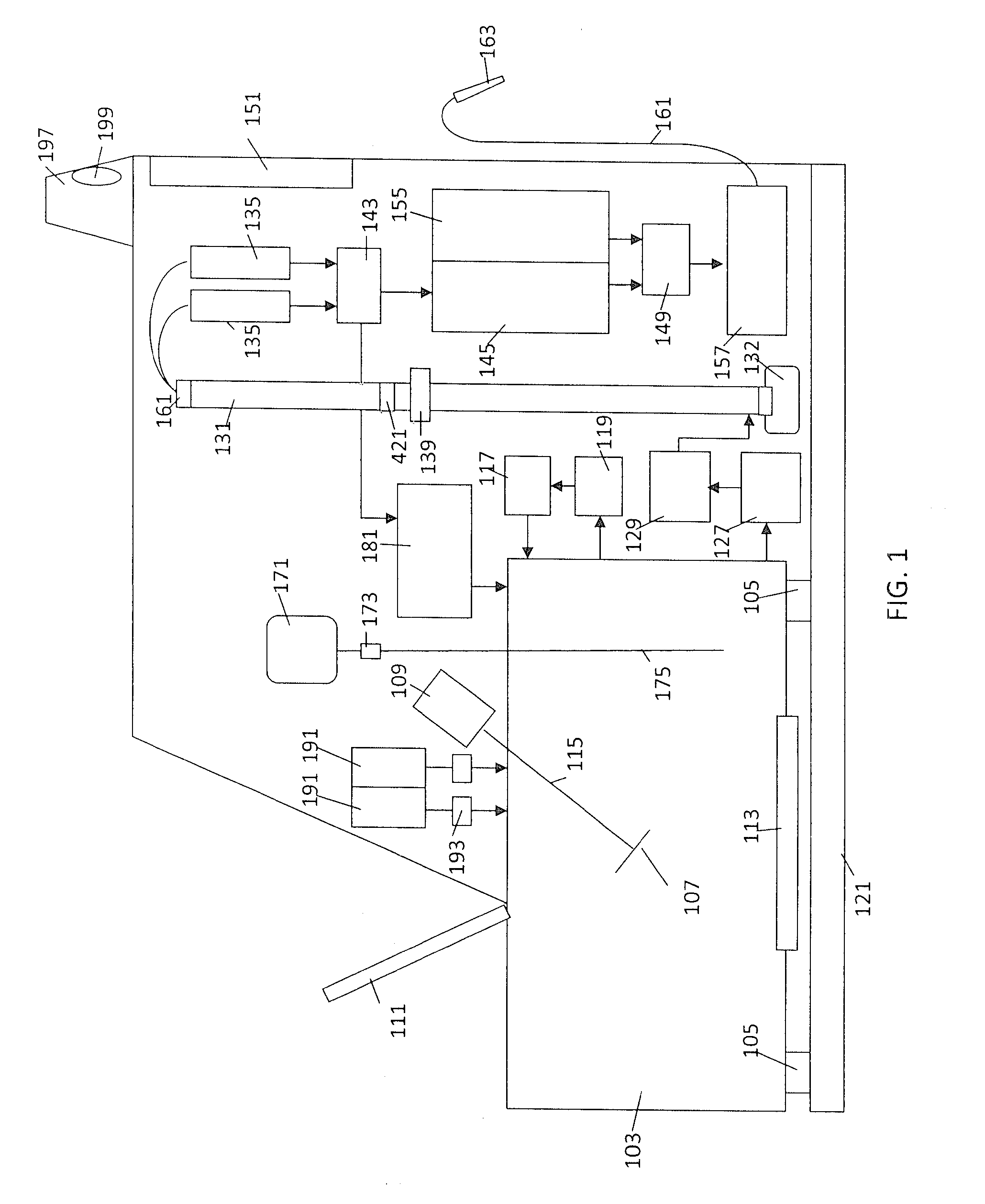
[0009]When the system is installed at a user's location and the user turns the micro refinery on, the system may go through a start up process to check each system for proper operation. Once the system is ready to begin processing, feedstock which includes sugar, yeast and yeast nutrients, is mixed with water in the fermentation tank. The fermentation tank is a sealed unit that includes an agitator, temperature control mechanisms and load cells. A measuring system detects the quantities of the feedstock components placed in the fermentation tank and the volume of water mixed with the feedstock so that the fermentation process can begin. A control system manages the pumps, agitator, valves, fans, sensors and thermoelectric coolers that automatically maintain the proper chemical mixture and fermentation environment. In this process yeast consumes sugar and converts it to ethanol, carbon dioxide gas and heat. In an embodiment, the system can monitor the fermentation process by detecting the carbon dioxide emitted and detecting the chemical components of the batch. The insertion of the feedstock can be done manually or automatically through actuated valves that control the flow of materials into the tank.
[0010]The system can detect the initial weight of the batch ingredients by monitoring the output signals from the load cells. If the feedstock components are input sequentially and individually, the weight of each component is represented by the change in weight as each feedstock component is added. Based upon the detected feedstock weight, the corresponding proper weight / volume of water can be calculated. The quantity of water inserted into the tank can be detected by the load cells or a flow measurement mechanism. In an embodiment, the tank can also have a sensor that detects the volume of liquid in the fermentation tank. The liquid sensor can include a float connected to a variable resistor within the tank. When the tank is full, the resistor is set to its low resistance value. As the tank empties, the float slides along the resistor altering the resistance. The downward movement can increase the electrical resistance of the liquid sensor and the resistance may reach its highest value when the tank is empty. The system may be calibrated to calculate the volume of liquid based upon the detected electrical resistance.
[0017]The distillation tube can be filled with material packing or horizontal perforated plates which are used to strip vaporized beer from the alcohol. Ideally, the vaporized beer and ethanol enter the bottom of the distillation tube and the beer vapor. Water and other heavier material are blocked by packing or plates. In contrast, the ethanol will tend to stay in vapor form and continue to travel up the distillation tube. This helps to separate the water and other contaminants from the ethanol vapor.
[0018]In an embodiment, multiple plates are vertically offset within the tube. However, in a preferred embodiment, the perforated plates that are angled diagonally are placed within the tube. The size of the holes in the perforated plates can be adjusted to optimize distillation performance. A potential problem occurs when the micro refinery has been running for a long time or temporarily stops production. The beer can remain on the packing or perforated plates within the condensation tube causing clogging of the perforations and / or packing. The entire condensation tube must then be cleaned before the system can operate at optimum efficiency. In order to reduce this clogging problem, the plates can be angled so that when water and beer vapor condenses on the plates, gravity will tend to draw the condensed liquid towards the lower edges of the plates. Because the beer liquids will tend to move away from the perforations and damage to the distillation tube is much less likely.
[0020]Vapors exiting the distillation tube are passed through a separation membrane that separates the ethanol from the other fluids. The membrane can be damaged by the thermal shock of being exposed to hot vapors too quickly. In order to prevent damage to the membrane from the hot vapors, the system may include a pre-heating mechanism and a temperature sensor that detects the membrane temperature. The pre-heating mechanism can be a heater that gradually heats the membrane before it is exposed to the hot vapors. The preheating can be controlled by a controller that can adjust the rate of heat increase to prevent damage to the membrane. When the membrane temperature is similar to the temperature of the hot water and ethanol vapors, the system can open a valve to allow the water and ethanol vapors to flow through the membrane.

Problems solved by technology

A problem with large industrial ethanol fermentation facilities is that the production requires large scale machinery that produces large batches of ethanol.

Method used


Image

  • Micro refinery for ethanol production
  • Micro refinery for ethanol production
  • Micro refinery for ethanol production

Examples


Embodiment Construction

[0040]The components of the inventive micro refinery system 101 will be described with reference to FIG. 1. In an embodiment the fermentation tank 103 rests on one or more load cells 105 that detect the downward force and produce corresponding electrical output signals. The load cells 105 are coupled to a system controller 151 that monitors the weight of the tank 103 and all contents within the tank 103 throughout the ethanol conversion process. The load cell 105 output signals are proportional to the detected weight. In an embodiment, the system controller 151 can go through a calibration process which detects the weight of the empty tank 103 and stores the empty tank weight as an offset value. The offset value can then be subtracted from any detected weight so that the system controller 151 can detect the weight and quantity of materials that are inserted into the tank 103. The fermentation tank 103 calibration process may be repeated each time a batch of materials is processed.

[0...


PUM


Abstract

A micro refinery system includes a fermentation tank, a distillation tube and a membrane ethanol separation mechanism. A batch that includes sugar, yeast and water is mixed in the fermentation tank. Sensors detect the physical characteristics of the batch and the operating status of the system. The sensors are coupled to a control system that compares the detected processing information to a look up table to determine if the system is operating under optimum ethanol productivity conditions. If the sensors detect a problem with the batch, the control system can add chemical components to the batch to correct the chemical imbalance. The system can also facilitate remote operations by transmitting sensed information to an operator computer and receiving control commands from the operator computer.

Description

CROSS REFERENCE TO RELATED APPLICATIONS[0001]This application is a continuation-in-part of U.S. patent application Ser. No. 12 / 110,242, “Method For Using Carbon Credits With Micro Refineries” filed on Apr. 25, 2008 and a continuation-in-part of U.S. patent application Ser. No. 12 / 110,158, “Micro Refinery System For Ethanol Production” filed on Apr. 25, 2008 which are both incorporated by reference.FIELD OF INVENTION[0002]The present invention relates generally to a system and method for remotely monitoring micro refinery ethanol systems that convert feedstock and / or discarded alcoholic liquids into ethanol and processing data from the micro refinery systems.BACKGROUND OF THE INVENTION[0003]Ethanol fermentation is the biological process by which sugars such as are converted into ethanol which can be used as fuel for internal combustion engines. Starch or sugar-based feedstocks can be used to produce ethanol or ethyl alcohol. Large fermenters are used to convert sugar and yeast into e...

Claims


Application Information

Patent Timeline
IPC IPC(8): C12M1/36C12M1/00
CPCC12M21/12C12M43/02C12M41/48
Inventor QUINN, THOMAS
Owner E FUEL CORP
Learn More