Method for making electrical windings for electrical apparatus and transformers and winding obtained by said method

Inactive Publication Date: 2009-12-24
PULNIKOV SERGEY
View PDF5 Cites 12 Cited by
  • Summary
  • Abstract
  • Description
  • Claims
  • Application Information

AI Technical Summary

Benefits of technology

[0013]A further object of the present invention is to allow a simple use of thermally conductive impregnating compounds.
[0014]A further object of invention is to provide a way of improving insulation between wires and neighboring layers.
[0015]A further object of invention is to provide insulation in accordance with local voltage gradient thereby improving efficiency of insulation between wires and neighboring layers.
[0016]A furth

Problems solved by technology

Oversizing these holders affects the size of the windings as well as the size of the whole device.
Copper wire cannot conform to abrupt variations in the winding direction.
This leads to a poor thermal contact between the winding and the holder.
In order to avoid overheating and insulation failure, the current density in the winding has to be reduced accordingly, which further increases space occupied by the winding.
Besides, polymer compounds used for impregnation of electric windin

Method used


Image

  • Method for making electrical windings for electrical apparatus and transformers and winding obtained by said method
  • Method for making electrical windings for electrical apparatus and transformers and winding obtained by said method
  • Method for making electrical windings for electrical apparatus and transformers and winding obtained by said method

Examples


Example

[0058]The proposed invention is related to the wide range of windings suited for low power transformers and inductors, medium power devices as well as for high voltage and high power devices.

[0059]There are specific requirements for each power range and each voltage range. In order to meet these requirements each step in the technology presented further has to be adopted accordingly.

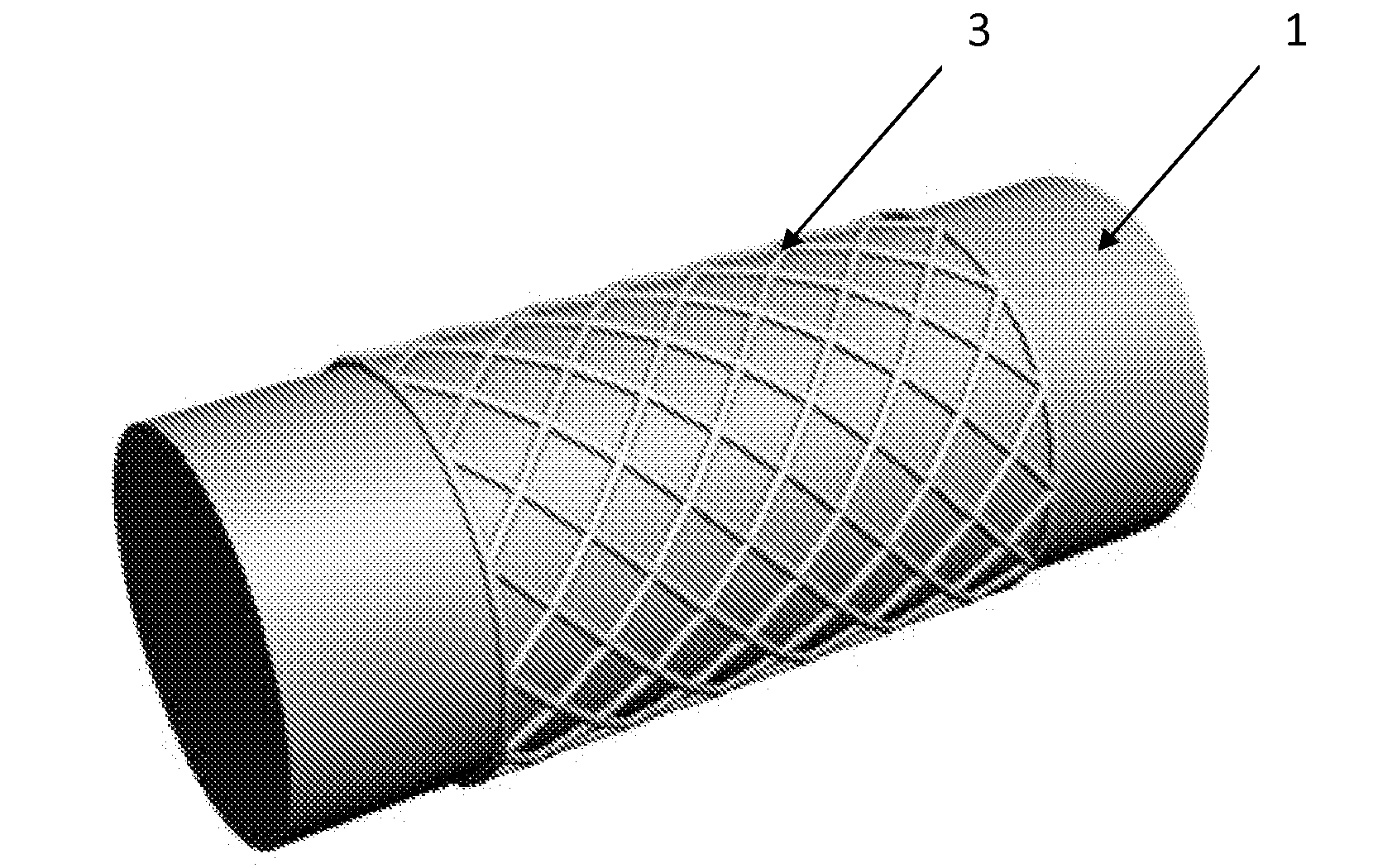
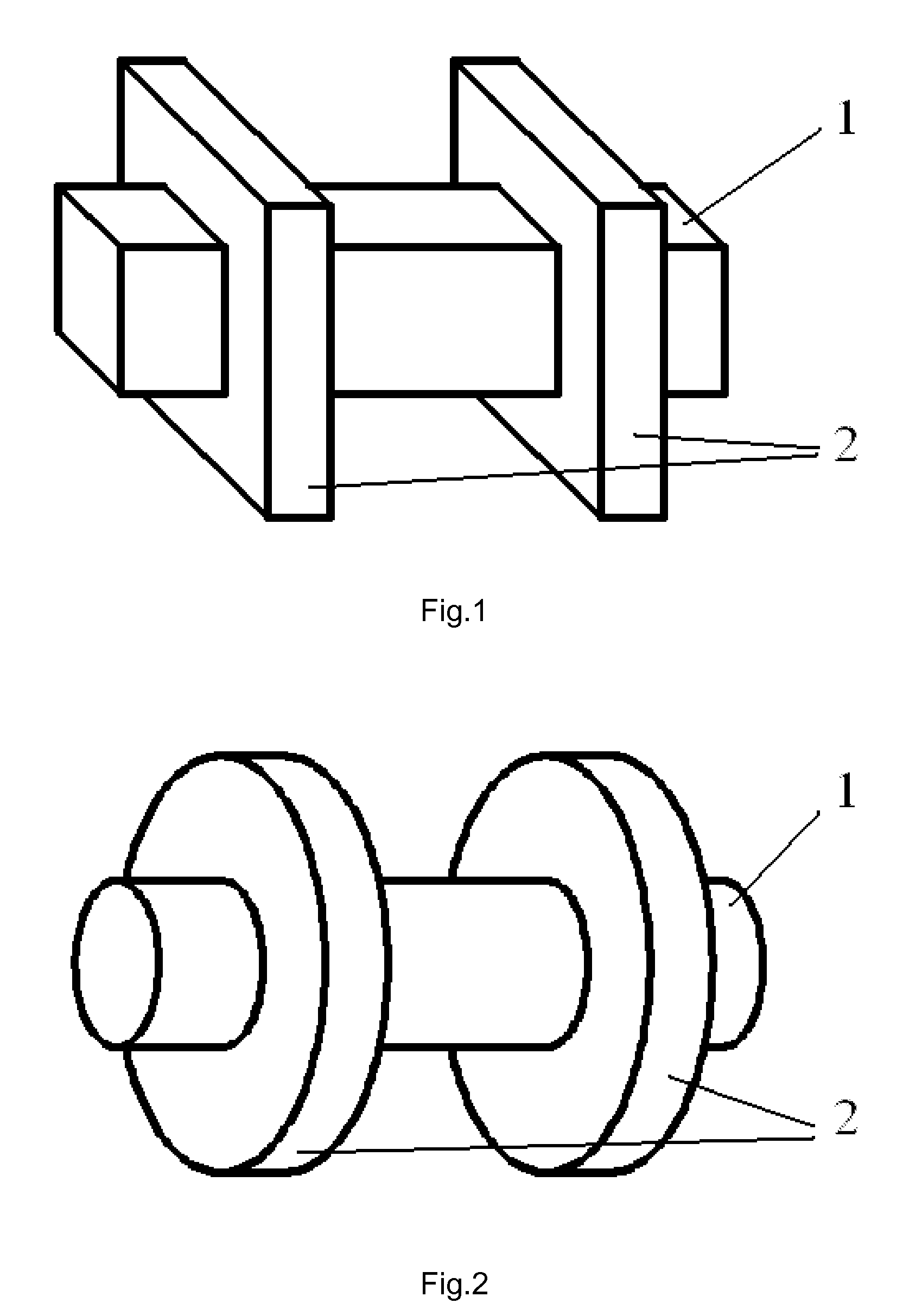
[0060]Referring to the drawings, FIG. 1 and FIG. 2 illustrate a construction of a mandrel 1 whereupon the winding is to be wound. The mandrel defines the internal shape of the winding. In most cases the shape of the mandrel should correspond to the shape of the magnetic core. The mandrel can have a slight taper in the direction of extraction of the winding. Mandrel can have chrome plating for protection against scratching. Some release agent should be applied on the mandrel in order to facilitate further extraction.

[0061]Preferable materials for the mandrel are steel or aluminum. In some occasions if ext...


PUM

PropertyMeasurementUnit
Pressureaaaaaaaaaa
Pressureaaaaaaaaaa
Angleaaaaaaaaaa

Abstract

This invention relates to a method of manufacturing electrical windings for electrical apparatus and transformers. This method comprises the following steps: manufacturing a metal mandrel defining the internal shape of the winding; installation of an internal insulation and support; installation of side rings; pouring impregnation compound on horizontally turning mandrel for obtaining a thin layer on the operational area of the mandrel and side surface of the side rings; optionally curing this layer; fixation of the first end wire using one of side rings; manufacturing winding with simultaneous pouring of compound onto the mandrel; possibly introducing intermediate insulation and/or reinforcing layers of preimpregnated reinforced plastics; optionally inserting premade sleeves around section of the winding; fixation of the second end wire using one of side rings; possibly introducing external insulation or reinforcing layers of preimpregnated reinforced plastics; possibly manufacturing secondary windings on top of the wound winding; curing the winding; extraction of the cured winding or a set of cured windings from the mandrel.
The invention also relates to winding structures obtained by this method.

Description

TECHNICAL FIELD[0001]This invention is related to the production of electrical windings for electrical apparatus and transformers. This invention is also related to the winding structure obtained by the said method.BACKGROUND INFORMATION[0002]This invention relates to a method of manufacturing electrical windings for electrical apparatus and transformers. This method comprises the following steps: manufacturing a metal mandrel defining the internal shape of the winding; installation of an internal insulation and support; installation of side rings; pouring impregnation compound on horizontally turning mandrel for obtaining a thin layer on the operational area of the mandrel and side surface of the side rings; optionally curing this layer; fixation of the first end wire using one of side rings; manufacturing winding with simultaneous pouring of compound onto the mandrel; possibly introducing intermediate insulation and / or reinforcing layers of preimpregnated reinforced plastics; opti...

Claims


Application Information

Patent Timeline
IPC IPC(8): H01F7/06
CPCH01F27/322H01F27/324H01F41/0633Y10T29/4902H01F41/127Y10T29/49071Y10T29/49073H01F41/0687H01F41/082H01F41/098
Inventor PULNIKOV, SERGEY
Owner PULNIKOV SERGEY
Why Eureka
Try Eureka