Concentration photovoltaic cell system with light guide

a photovoltaic cell and light guide technology, applied in the field of photovoltaic cells, can solve the problems of high cost inefficient method of utilizing photovoltaic cells to convert solar energy into electric energy, and high cost per watt of solar power generation, so as to reduce energy conversion efficiency

Inactive Publication Date: 2009-12-31
ARIMA ECOENERGY TECH
View PDF5 Cites 7 Cited by
  • Summary
  • Abstract
  • Description
  • Claims
  • Application Information

AI Technical Summary

Benefits of technology

[0006]A primary object of the present invention is to provide a concentration photovoltaic cell system with light guide, in which a solar energy converter is not directly exposed to sunlight to avoid the reduced energy conversion efficiency caused by temperature rising at photovoltaic cell chips thereof.

Problems solved by technology

Generally speaking, a photovoltaic cell system must require a large amount of expensive photovoltaic material.
Up to date, there is not an efficient method for utilizing photovoltaic cells to convert solar energy into electric energy.
Therefore, the current unit cost (dollar per watt) of solar power generation is very expensive.
However to ensure the proper focusing of sunlight onto the chip, a tracker is required to constantly orient the cells toward the sunlight, which also occupies additional space and is relatively heavy.
When the tracker is not accurately oriented toward the sunlight, the solar energy efficiency of the CPV system is drastically reduced.
In this manner, the temperature of the chip 2 tends to increase and consequently the chip's solar conversion efficiency is adversely reduced.

Method used


Image

  • Concentration photovoltaic cell system with light guide
  • Concentration photovoltaic cell system with light guide
  • Concentration photovoltaic cell system with light guide

Examples


first embodiment

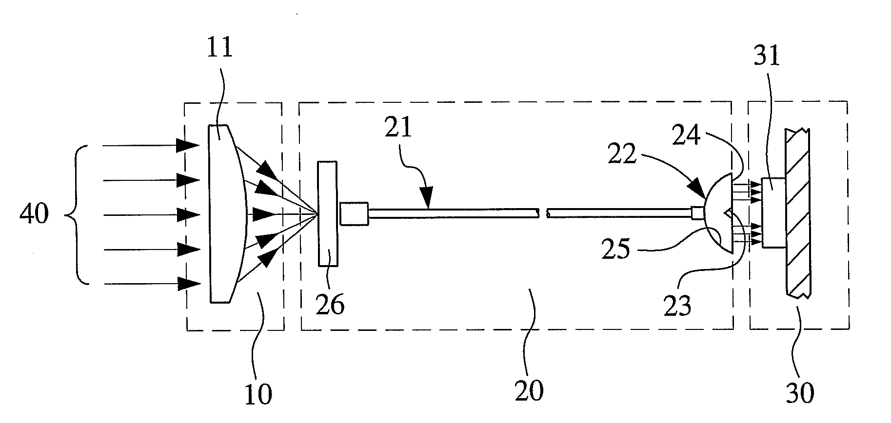
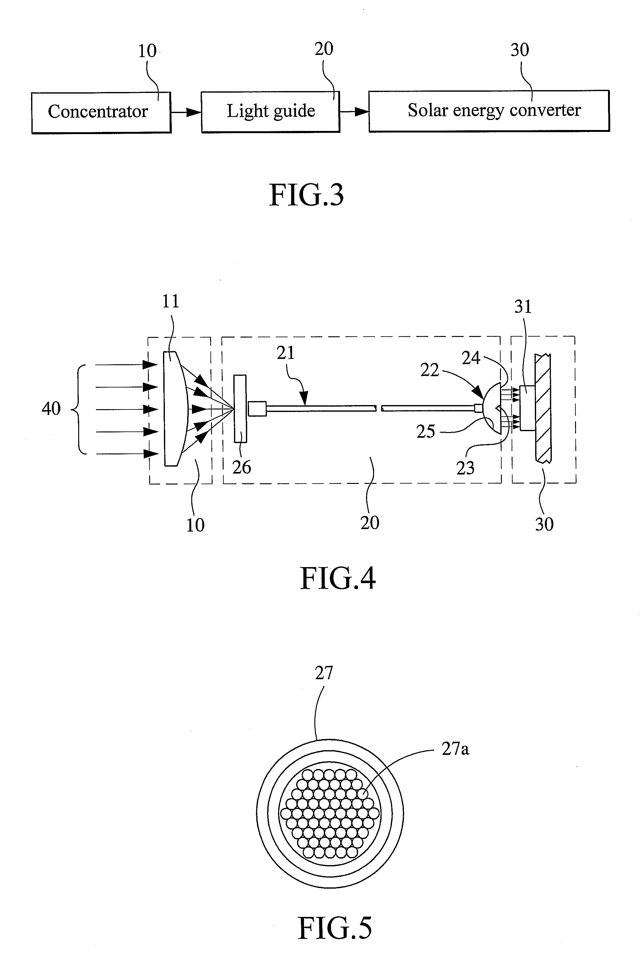
[0033]FIG. 5 is a cross sectional view of the optical fiber cable 27 adopted in the contraction photovoltaic cell system of the present invention, and FIG. 6 shows the lens assembly 22 used with the optical fiber cable 27. As can be seen from FIG. 5, the optical fiber cable 27 may contain one single optical fiber 27a for the usage with a photovoltaic cell having a relatively small area, or a plurality of optical fibers 27a for the usage with a photovoltaic cell having a relatively large area, depending on actual need in design. As shown in FIG. 6, when the focused light propagates through the light guide 20 to the lens assembly 22, the light projects from the optical fibers 27a of the optical fiber cable 27 to the reflective mirror 25, and is then reflected by the reflective mirror 25 onto the photovoltaic cell chip 31 of the solar energy converter 30, and converted into electric energy.

second embodiment

[0034]FIG. 7 shows the concentration photovoltaic cell system according to the present invention, in which a light guiding plate 28 is adopted as the light guiding medium 21, and FIG. 8 shows the lens assembly 22 used with the light guiding plate 28. The light guiding plate 28 may have a variable thickness according to the actual design need. The light guiding plate 28 is aligned with the light splitter 23. When the focused light propagates through the light guiding plate 28 to the lens assembly 22, the light projects from the light guiding plate 28 to the pyramidal light splitter 23, and is reflected onto the reflective mirror 25 before being further reflected by the reflective mirror 25 to the photovoltaic cell chip 31 of solar energy converter 30 and converted into electric energy.

[0035]Alternatively, the pyramidal light splitter 23 may be replaced with a curved light splitter (not shown) to provide the same light reflecting effect.

[0036]FIG. 9 shows a concentration photovoltaic ...


PUM


Abstract

A concentration photovoltaic cell system with light guide includes a concentrator for focusing sunlight; a light guide located at where the sunlight is focused by the concentrator, so that the focused light is fully coupled to an input end of the light guide and propagates to an output end of the light guide; and a solar energy converter arranged at the output end of the light guide for receiving and converting the light projected from the light guide into electric energy. With the above arrangements, the solar converter may be located at a place not exposed to sunlight to avoid lowered energy conversion efficiency caused by temperature rising at photovoltaic cell chips thereof, and the use of the light guide enables increased GCR and light concentrating efficiency to enable reduced number of expensive photovoltaic cells.

Description

FIELD OF THE INVENTION[0001]The present invention relates to a photovoltaic cell, and more specifically, to a concentration photovoltaic (CPV) cell system with light guide.BACKGROUND OF THE INVENTION[0002]A photovoltaic cell employs the photovoltaic effect to convert solar light energy into electric energy and thereby achieving the purpose and benefits of power generation. According to the currently available techniques, the photovoltaic cell is directly exposed to sunlight for receiving and converting the solar energy into electric energy.[0003]Generally speaking, a photovoltaic cell system must require a large amount of expensive photovoltaic material. Up to date, there is not an efficient method for utilizing photovoltaic cells to convert solar energy into electric energy. Therefore, the current unit cost (dollar per watt) of solar power generation is very expensive. To reduce the manufacturing cost of photovoltaic cell modules, external mechanisms and optical elements have been ...

Claims


Application Information

Patent Timeline
Patent Type & Authority Applications(United States)
IPC IPC(8): H01L31/042
CPCY02E10/52H01L31/0547H01L31/0543
Inventor LEE, SEN-TIENTZENG, YEN-CHANGHSU, CHIN-WEIHUANG, CHUNG-YI
Owner ARIMA ECOENERGY TECH
Why Eureka
Try Eureka