Sulfuric acid electrolysis process

a technology of sulfuric acid and electrolysis process, which is applied in the direction of electrolysis process, electrolysis components, cells, etc., can solve the problems of difficult to liberate the generated gas from the electrode surface, the bubbles formed by the liberated gas in the electrolyte take time to diffuse, and the wash stripping efficiency of photoresist, etc., to achieve the effect of improving the electrolysis efficiency and reducing the cost of electrolysis

Active Publication Date: 2009-12-31
KK TOSHIBA +2
View PDF1 Cites 9 Cited by
  • Summary
  • Abstract
  • Description
  • Claims
  • Application Information

AI Technical Summary

Benefits of technology

[0018]The present invention aims to eliminate the weak points of the conventional technologies described in Patent Documents 1-3 in view of said characteristics of the viscosity and the coagulation point of concentrated sulfuric acid described in Non-Patent Document 1, in particular, the present invention prevents the troubles of electrolytic operation failure during said electrolysis from occurring at 70% by mass or more of concentrated sulfuric acid concentration, and at 20 A / dm2 or more of the current density, by offering the sulfuric acid electrolysis process to form oxidizing agent stably through direct electrolysis of concentrated sulfuric acid by using the conductive diamond anode.

Problems solved by technology

However, electrolysis of the aqueous Sulfate solution at such relatively low concentration as shown in Patent Document 1 reveals a problem that the wash stripping efficiency of photoresist, etc. is low.
However, concentrated sulfuric acid has such features derived from its high viscosity with less fluidity, compared with water or relatively thin aqueous solution, that when it is used as an electrolyte for electrolysis, the generated gas from the electrolysis is hard to be liberated from the electrode surface, and also bubbles formed by liberated gas in the electrolyte take time to diffuse and therefore, are difficult to be discharged outside the electrolytic cell.
Accordingly, if such gas covers the electrode surface or is contained in the electrolyte plentifully, the resistance between the anode and the cathode increases, raising the cell voltage, which may eventually lead to a phenomenon that electrolytic current will not be supplied in excess of the maximums supply output of the power source, which interferes with the production process of persulfuric acid.
When precipitate, they will also become a factor to interfere with electrolytic current flow as with the case of gas.
Meanwhile, such troubles have often happened that when in the sulfuric acid electrolysis process to manufacture persulfuric acid using the conductive diamond anode as described in Patent Document 2 and Patent Document 3, electrolytic current value is raised to operate the electrolysis cell, the cell voltage sharply rise beyond the limit of the connected rectifier within a short period of time and the set-up current value sharply descends, causing failure of electrolysis operation.
In particular, such trouble of failure in electrolysis was significant when the concentration of concentrated sulfuric acid in said electrolysis was 70% by mass or more and the current density was 20 A / dm2 or more in said electrolysis.
It is presumed that to a small variation of concentration, the property changes significantly, and that near the coagulation point, viscosity varies considerably and said troubles tend to easily occur.
In order to promote gas elimination in the region of a high sulfuric acid concentration, applied temperature must be raised, which, however, is known undesirable due to increased decomposition of persulfuric acid.

Method used


Image

  • Sulfuric acid electrolysis process
  • Sulfuric acid electrolysis process

Examples


example [UNK]

EXAMPLE 1˜6

[0076]The following gives an example of the operation method of the sulfuric acid electrolytic cell by the present invention.

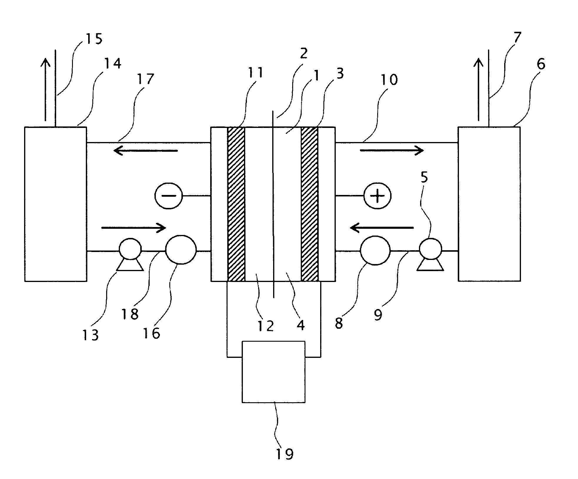
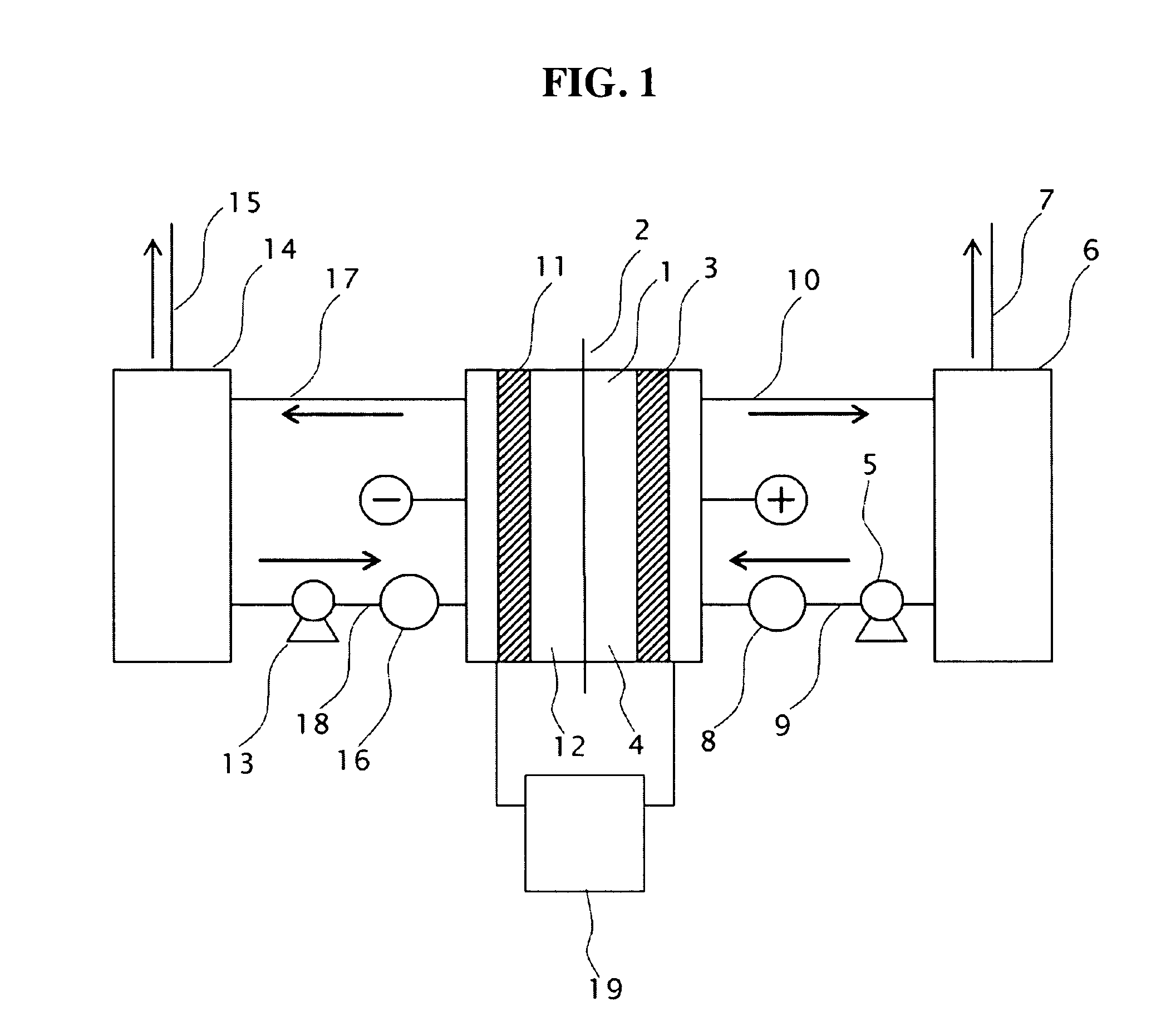
[0077]Two electrodes with the conductive diamond film formed on 6-inch dia. silicon substrates were opposingly installed as anode 3 and cathode 11 with a porous PTFE diaphragm inserted in between. The gap between the electrode and the diaphragm was 6 mm, respectively both for the anode and the cathode to constitute an electrolytic cell, as described in FIG. 1, having an effective electrolysis area of 1 dm2.

[0078]Raw material sulfuric acid was stored in the anolyte tank 6 and the catholyte tank 14; sulfuric acid was supplied to the anode compartment 4 and the cathode compartment 12 of the electrolytic cell 1 at a given flow rate by the circulation pumps 5, 13 installed on the lines of the anode side and the cathode side; and electrolysis was performed with electric power supplied across the electrodes. The electrolytic current was supplied from the p...


PUM

PropertyMeasurementUnit
electrolytic currentaaaaaaaaaa
current densityaaaaaaaaaa
viscosityaaaaaaaaaa

Abstract

Sulfuric acid electrolysis process wherein;a temperature of electrolyte containing sulfuric acid to be supplied to an anode compartment and a cathode compartment is controlled to 30 degree Celsius or more;a flow rate F1 (L / min.) of the electrolyte containing sulfuric acid to be supplied to said anode compartment is controlled to 1.5 times or more (F1 / Fa≧1.5) a flow rate Fa (L / min.) of gas formed on an anode side as calculated from Equation (1) shown below and a flow rate F2(L / min.) of said electrolyte containing sulfuric acid to be supplied to said cathode compartment is controlled to 1.5 times or more (F2 / Fc≧1.5) a flow rate Fe (L / min.) of gas formed on a cathode side as calculated from Equation (2) shown below.Fa=(I×S×R×T) / (4×Faraday constant)   Equation (I)Fe=(I×S×R×T) / (2×Faraday constant)   Equation (2)I: Electrolytic current (A)S: Time: 60 second (Fixed)R: Gas constant (0.082 1·atm / K / mol)K: Absolute temperature (273.15 degree Celsius+T degree Celsius)T: Electrolysis temperature (degree Celsius)Faraday constant: (C / mol)

Description

CROSS-REFERENCE TO RELATED APPLICATIONS[0001]This application is based upon and claims the benefit of priority of Japanese Patent Application 2008-170097, filed on Jun. 30, 2008; the entire contents of which are incorporated herein by reference.BACKGROUND OF THE INVENTION[0002]1. Field of the Invention[0003]The present invention relates to the sulfuric acid electrolysis process which directly electrolyzes concentrated sulfuric acid by using the conductive diamond anode to form oxidizing agent stably.[0004]2. Description of the Related Art[0005]In the so-called wet washing technology, where silicon wafer works are objects of cleaning as seen in the semiconductor device manufacturing, persulfuric acid or persulfate is used as removing agent for used photoresist, metals and organic pollutants. These persulfuric acid or persulfate are known to form through the electrolysis of sulfuric acid, and already manufactured electrolytically on an industrial scale. (Patent Document 1)[0006]Patent...

Claims


Application Information

Patent Timeline
Patent Type & Authority Applications(United States)
IPC IPC(8): C25B15/00C25B9/19
CPCC25B1/285C25B1/29C25B11/04C25B9/23C25B15/083
Inventor KATO, MASAAKIOGAWA, YUSUKEDOMON, HIROKIHAYAMIZU, NAOYATANGE, MAKIKOKUROKAWA, YOSHIAKIKOBAYASHI, NOBUO
Owner KK TOSHIBA
Why Eureka
Try Eureka