Tidal power apparatus

a technology of power apparatus and tide, which is applied in the direction of propulsive elements, water-acting propulsive elements, motors, etc., can solve the problems of affecting the stability of the ecosystem, the inability to find suitable locations for such schemes, and the risk of permanent changes in the ecosystem of the area, so as to simplify the construction and operation, the effect of simplifying construction and maintenan

Inactive Publication Date: 2009-12-31
NEPTUNE RENEWABLE ENERGY
View PDF8 Cites 28 Cited by
  • Summary
  • Abstract
  • Description
  • Claims
  • Application Information

AI Technical Summary

Benefits of technology

[0020]The rotor is preferably cross-flow turbine, more preferably a Banki turbine as described by Mockmore and Merryfield in 1949 (“The Banki Water Turbine”, Oregon State College, Bulletin Series No 25, February 1949), but configured with a vertical axis of rotation. This type of turbine has a plurality of shaped vanes arranged around, but spaced from, a central axle, offering the advantage that potentially clogging materials, such as seaweed, will be flushed clear of the rotor by the emerging water, assisted by centrifugal force. Conventionally, this type of turbine is configured with a horizontal axis and a vertical head of water typically of 1-200 m. It has been found that a vertical rotor, in conjunction with reversible deflector vanes, offers advantag...

Problems solved by technology

Several major tidal power schemes have been constructed in river estuaries, but these have involved barrages and major engineering works, and they risk permanent c...

Method used


Image

  • Tidal power apparatus
  • Tidal power apparatus
  • Tidal power apparatus

Examples


Embodiment Construction

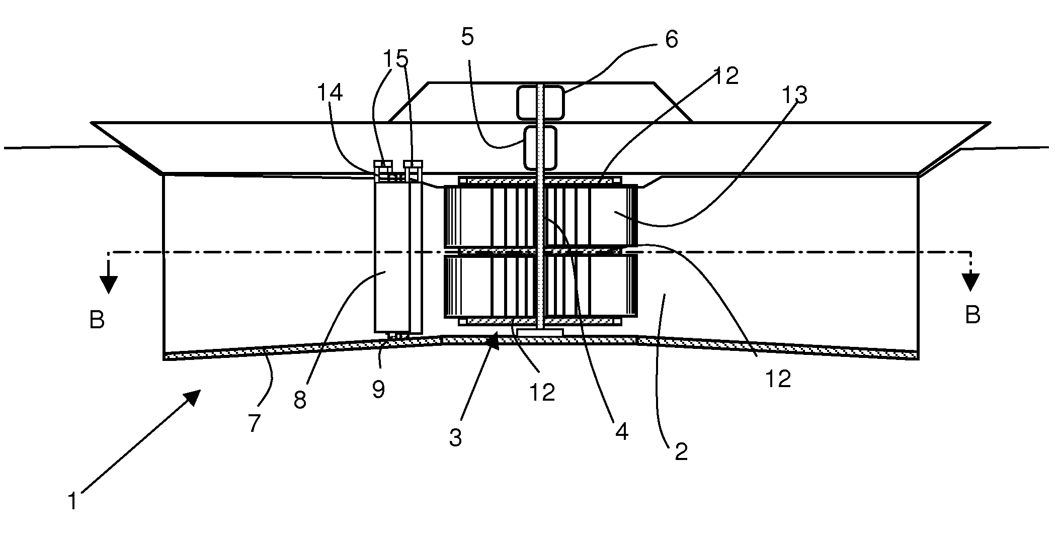
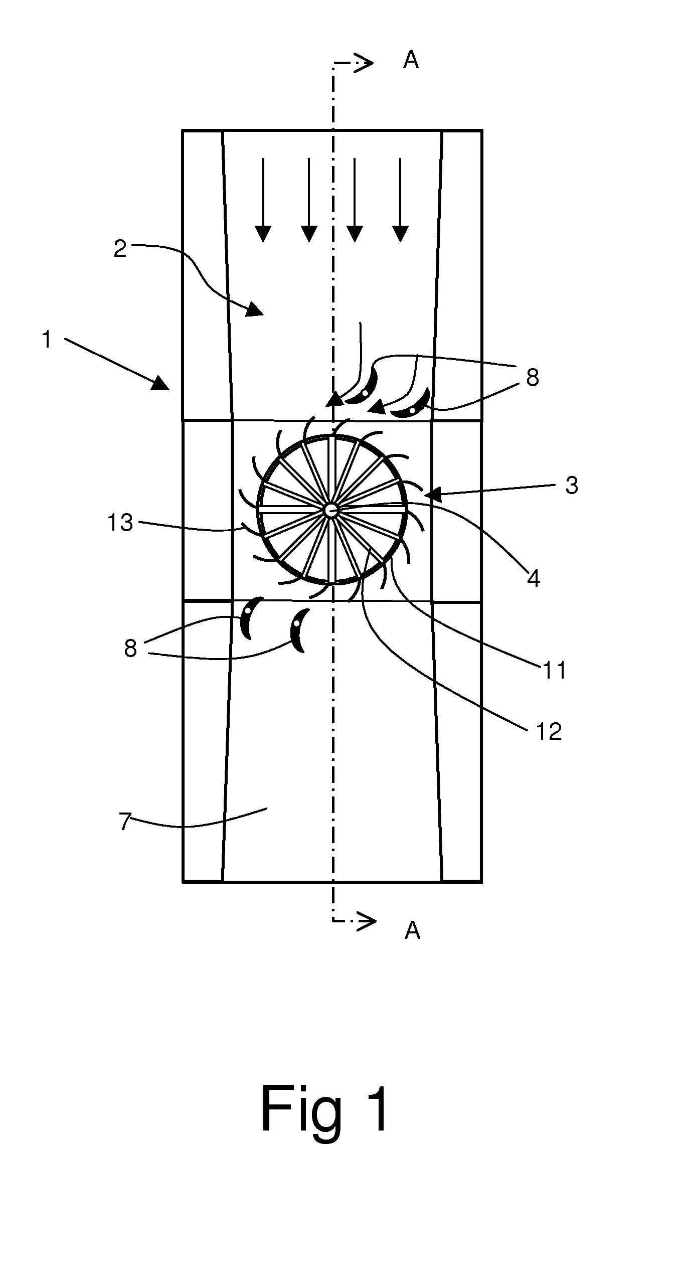
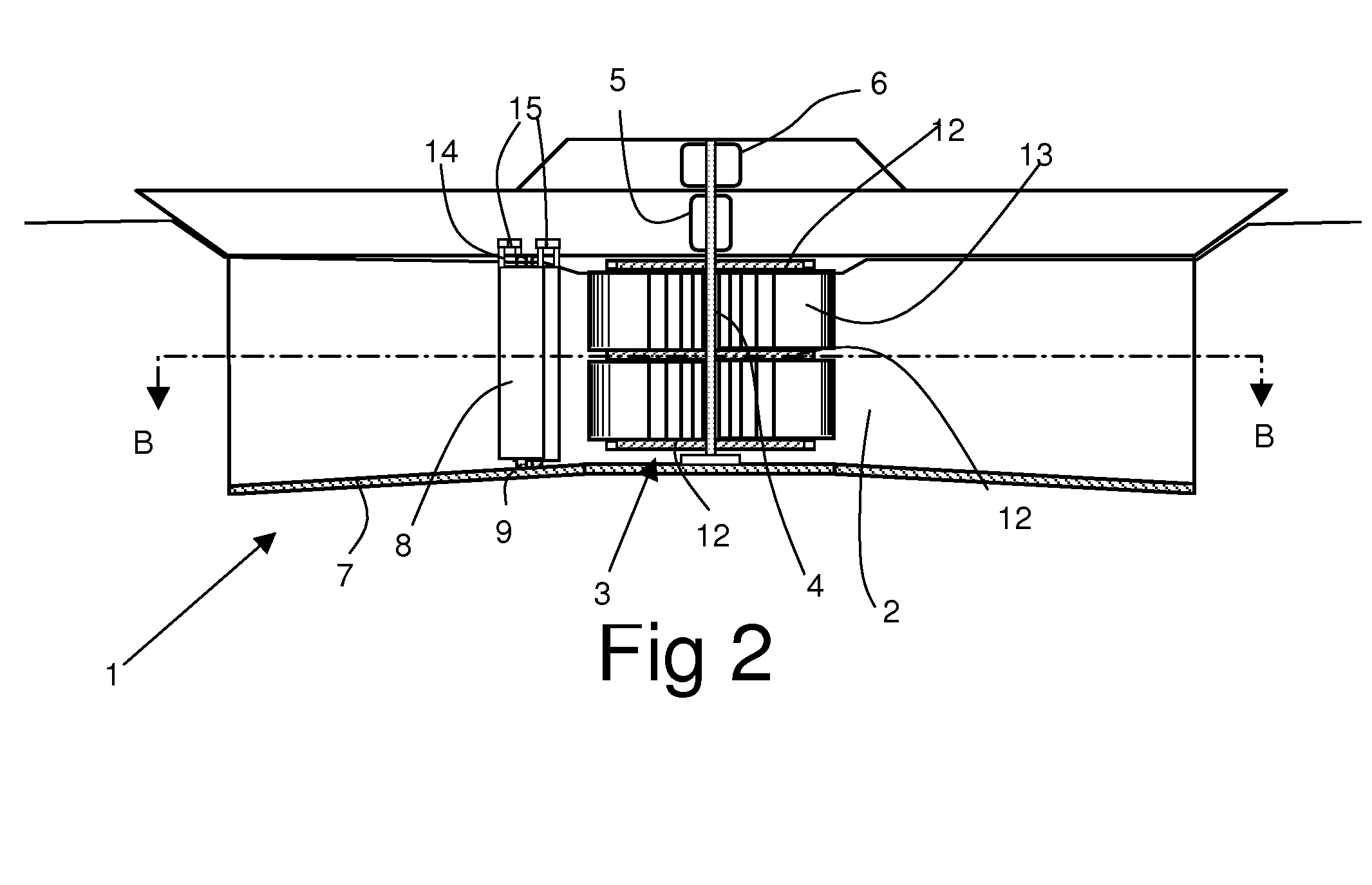
[0026]The apparatus consists of a floating pontoon 1 having a hollow duct 2 therethrough opening at each end of the pontoon. A turbine 3 is mounted in the duct 2 on a vertical axle 4 which is supported by a bearing 5 at the upper end thereof and which turns an electrical alternator 6 located above the bearing. In practice, a pair of variable speed, variable torque alternators will be provided, driven from the shaft, to provide redundancy, ensuring continuity of supply. Each alternator will normally run at a mean power of about 100 kW, but very exceptionally at 250 kW, so the maximum installed capacity is 500 kW. The alternators feed through AC / DC / AC converters to provide mains synchronised connection through a submarine cable to the electricity grid. The generators also supply low voltage power for the control system, for onboard battery charging (providing emergency power in the event of generator or other failure), and for navigational and deck lighting.

[0027]The duct is preferabl...


PUM


Abstract

A tidal power apparatus comprises a moored pontoon (1) having a duct (2) therethrough opening at opposed ends of the pontoon. The duct has a vertical axis rotor (3) therein driving an electrical generator (6). A deflector vane (8) is located in the duct at each end thereof, each deflector vane being mounted to pivot about a vertical axis between an active position, in which the deflector vane deflects water flow to one side of the rotor axis to cause rotation of the rotor, and an inactive position substantially aligned with the water flow from the turbine.

Description

FIELD OF THE INVENTION[0001]This invention relates to apparatus for extracting energy from tidal flows.BACKGROUND TO THE INVENTION[0002]Tidal power devices offer advantages over wave power devices: tides are regular and predictable, whereas wave power depends essentially upon weather conditions; and lower device masses can be employed at coastal sites, because locations for tidal devices are generally exposed to less extreme weather and the devices do not therefore have to be constructed to the same level of survivability as ocean wave power devices.[0003]Several major tidal power schemes have been constructed in river estuaries, but these have involved barrages and major engineering works, and they risk permanent changes to ecosystems in areas of importance to wildlife. They are extremely costly to build, and it is increasingly difficult to find suitable locations for such schemes.[0004]There have been several proposals for smaller-scale, in stream, tidal power devices that have le...

Claims


Application Information

Patent Timeline
IPC IPC(8): F03B13/26
CPCF03B13/264F03B17/063Y02E10/28F05B2240/93F05B2240/932F05B2240/12Y02E10/30Y02E10/20
Inventor JACK, HARDISTY
Owner NEPTUNE RENEWABLE ENERGY
Why Eureka
Try Eureka