Charged particle beam apparatus

a charge-pulverized particle and beam technology, applied in the field of charge-pulverized particle beam apparatus, can solve the problems of not making mention of their specific applications, prior art techniques that fail to meet the foregoing requirements in those applications, and various harmful effects are produced in acquiring left-right symmetric images

Active Publication Date: 2009-12-31
HITACHI HIGH-TECH CORP
View PDF2 Cites 36 Cited by
  • Summary
  • Abstract
  • Description
  • Claims
  • Application Information

AI Technical Summary

Benefits of technology

[0015]According to the present invention, a stereoscopic image is created from images derived by beam tilting corresponding to the angle of the left-right parallax. Consequently, real-time stereoscopic imaging and its application are made possible.

Problems solved by technology

However, no mention is made of their specific applications.
Hence, these prior art techniques fail to meet the foregoing demands in those applications.
However, various harmful effects are produced in acquiring left-right symmetric images.
Insufficient reproducibility of the field of view, a growing worse in the symmetry of the image pair due to insufficient reproducibility of the tilt angle of the imaged subject, and a growing worse in the brightness symmetry due to an excessive increase in the contrast caused by damage to the specimen have placed limitations on stereoscopic imaging relying on the prior art.

Method used


Image

  • Charged particle beam apparatus
  • Charged particle beam apparatus
  • Charged particle beam apparatus

Examples


Embodiment Construction

[0033]Embodiments of the present invention are hereinafter described with reference to the drawings.

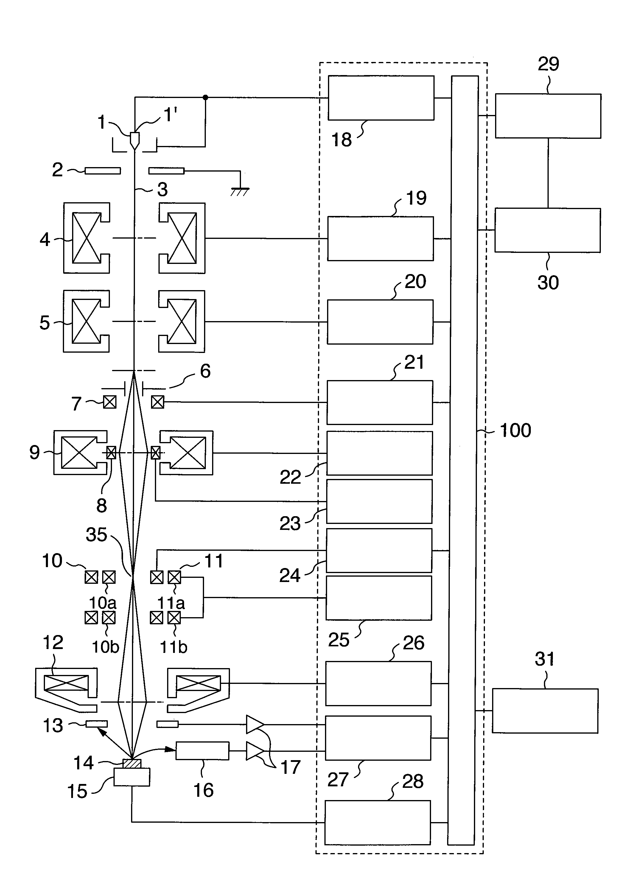
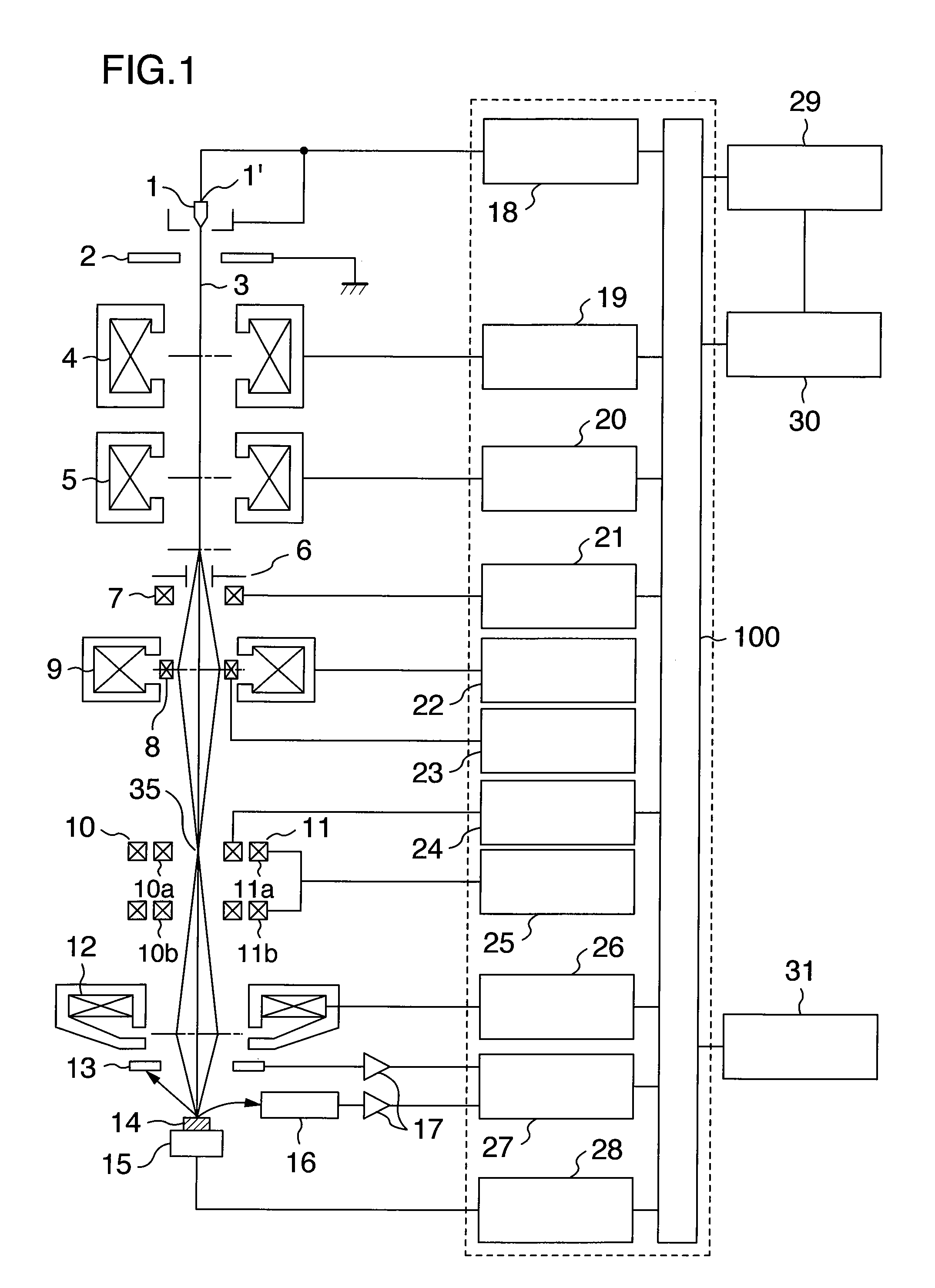
[0034]FIG. 1 is a schematic diagram of a scanning electron microscope according to one embodiment of the present invention.

[0035]The microscope has an electron gun 1′ forming a charged particle beam source. The gun 1′ is comprised of a cathode 1 and an anode 2. The microscope further includes a high-voltage control power supply 18 that applies a voltage between the cathode 1 and the anode 2 under control of a computer 28 acting as a control unit. A primary electron beam 3 acting as a primary charged particle beam is extracted from the cathode 1 and accelerated and guided toward a rear stage of lenses via acceleration anodes (not shown).

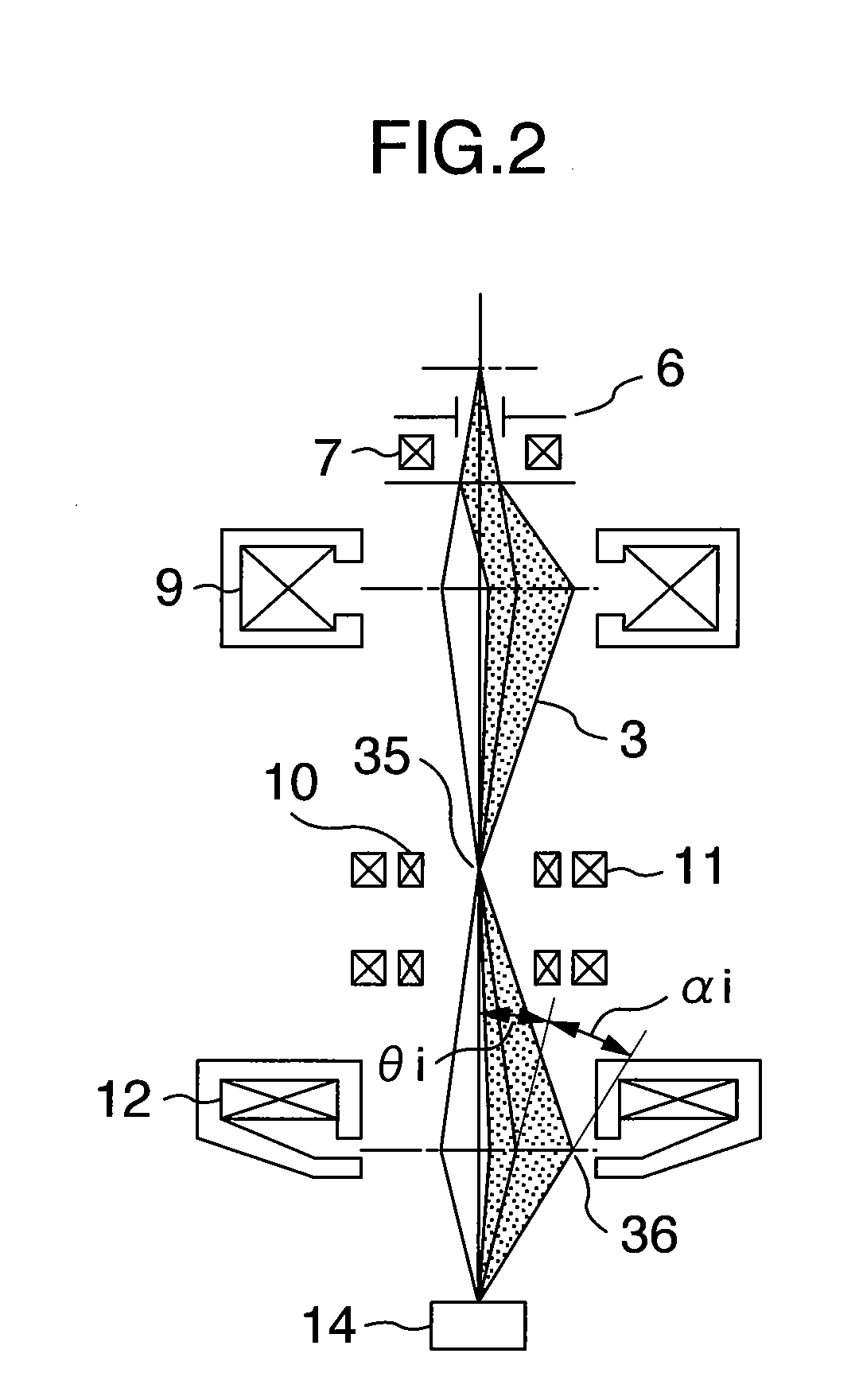
[0036]The primary electron beam 3 is focused by a first condenser lens 4 under control of a first condenser lens control power supply 19 and further focused by a second condenser lens 5 under control of a second condenser lens control power supply 20. T...


PUM

PropertyMeasurementUnit
parallactic angleaaaaaaaaaa
angleaaaaaaaaaa

Abstract

A charged particle beam impinging on a specimen is set to have left and right tilt angles corresponding to a parallactic angle. A control unit is provided which scans the beam over the specimen while giving a left tilt and a right tilt corresponding to the parallactic angle alternately to the beam on each scanning line. In this way, images are acquired. A three-dimensional image in which deterioration of the resolution is suppressed is displayed in real time by combining aberration cancellation means with the control of the beam according to the parallactic angle. The aberration cancellation means uses an optical system having plural stages of lenses to provide overall cancellation of aberrations by making use of the action of a lens to deflect the beam back to the optical axis.

Description

BACKGROUND OF THE INVENTION[0001]The present invention relates to a charged particle beam apparatus for controllably scanning a charged particle beam (such as an electron beam or ion beam) over a specimen to obtain a final image and, more particularly, to a charged particle beam apparatus adapted to obtain stereoscopic, three-dimensional images.[0002]In a charged particle beam apparatus typified by a scanning electron microscope, a sharply focused charged particle beam is scanned over a specimen to obtain desired information (e.g., images of the specimen) from the specimen. In such a charged particle beam apparatus, stereoscopic imaging has been heretofore done utilizing a crossed view method, a parallel view method, or an anaglyph method using the human eye visual perception. In the crossed method or parallel method, the specimen is tilted left and right with respect to the scanning beam. Two still images or two still photographs are acquired from different orientations. Then, ster...

Claims


Application Information

Patent Timeline
Patent Type & Authority Applications(United States)
IPC IPC(8): G02F1/1335G01K1/08G02B27/22
CPCH01J37/1478H01J37/153H01J2237/2611H01J37/28H01J37/265
Inventor ITO, SUKEHIROKATANE, JUNICHIKAWAMATA, SHIGERUTOMITA, SHINICHI
Owner HITACHI HIGH-TECH CORP
Why Eureka
Try Eureka