

Manufacture of high temperature superconductor coils
a superconductor coil and high temperature technology, applied in the direction of superconductors/hyperconductors, line/current collector details, electrical equipment, etc., can solve the problems of difficult to remove unwanted gas, difficult to purge trapped cosub>2, and many defects in the internal winding of the 2212 coil
- Summary
- Abstract
- Description
- Claims
- Application Information
AI Technical Summary
Benefits of technology
Problems solved by technology
Method used
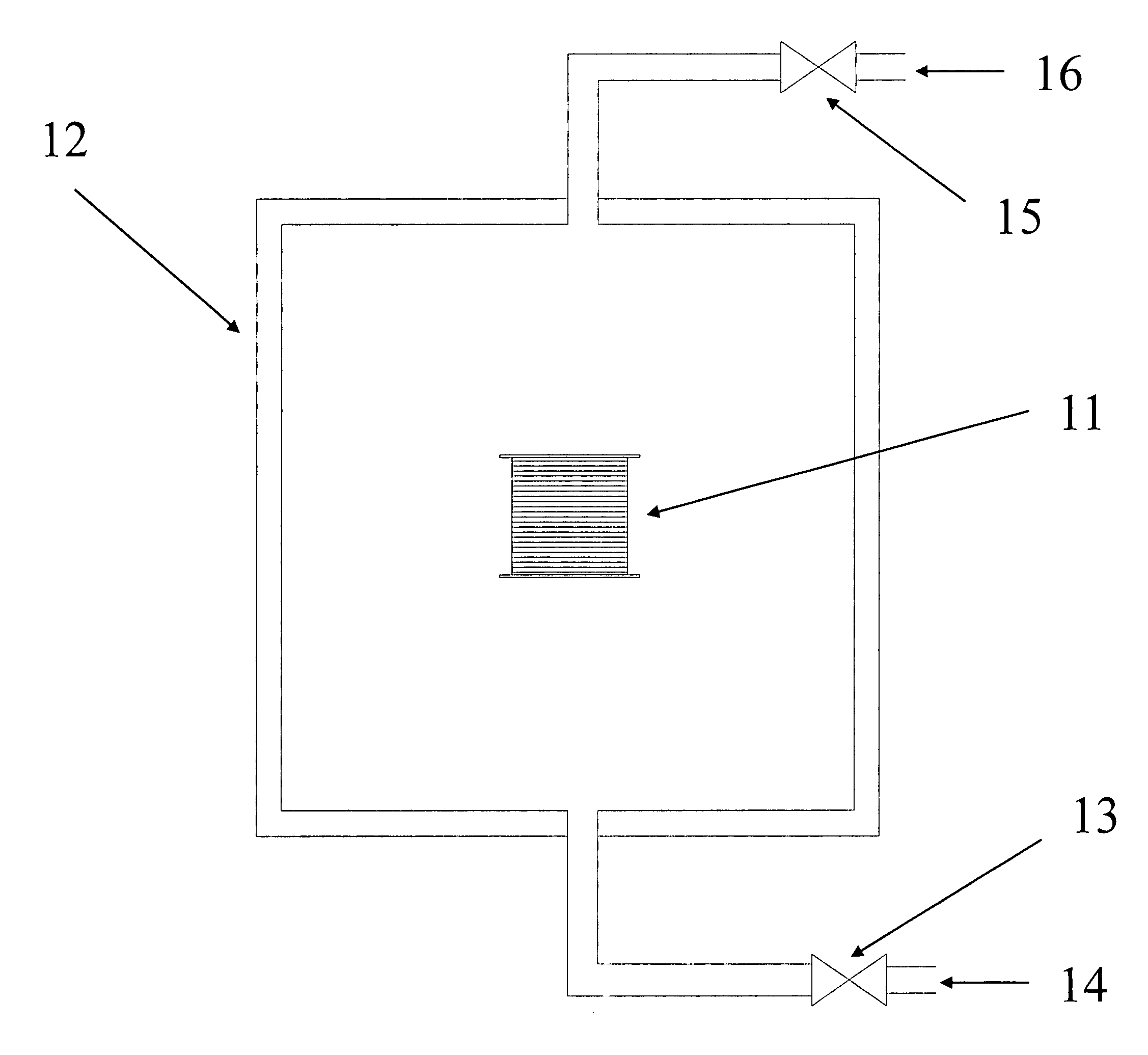
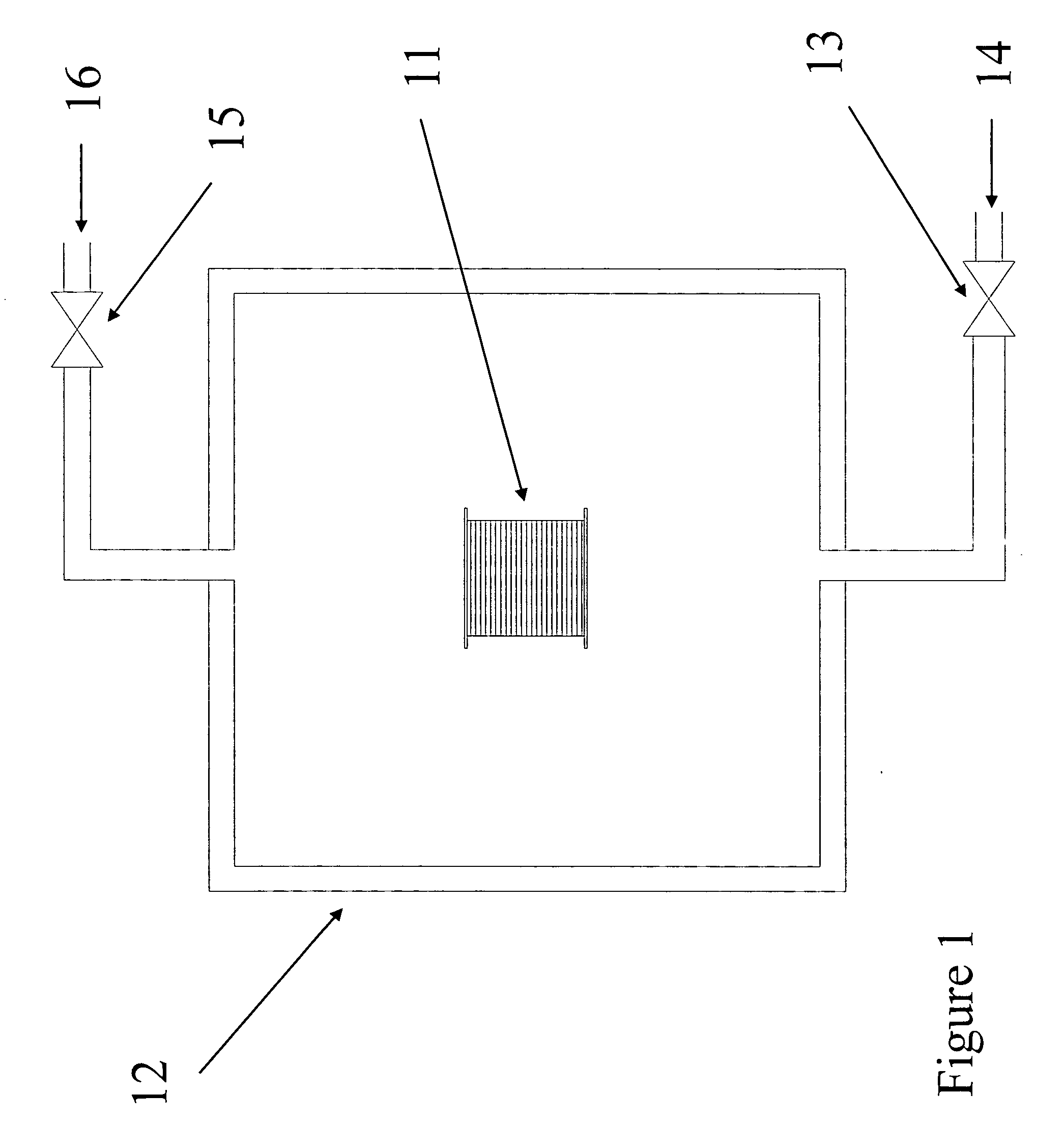
Image

Examples
example
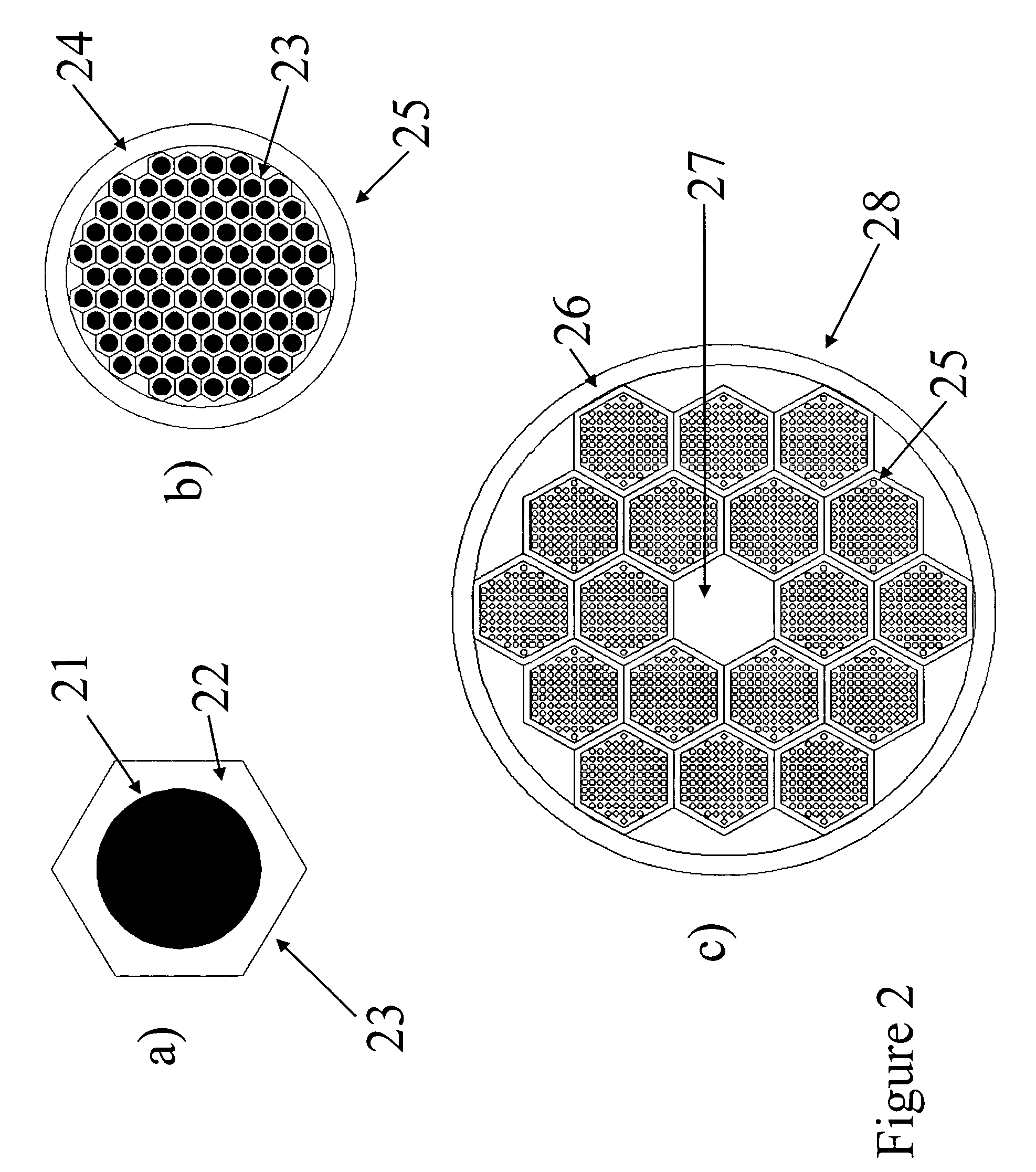
[0016]Bi-2212 precursor powders with cation stoiciometery of Bi:Sr:Ca:Cu of 2.17:1.94:0.89:2.0 made by the melting-casting process were purchased from Nexans SuperConductors GmbH. As per FIG. 2, and described in prior art, the starting Bi-2212 precursor powder 21 was packed in a pure silver tube 22 as per prior art high temperature superconductor powder-in-tube methods. As shown at a) these powder tubes were drawn and hexed to 2.29 mm flat-to-flat (FTF) and cut into lengths of 460 mm forming the mono-core hexes 23. At b) eighty-five of these mono-core hexes were bundled and stacked into another silver tube 24, forming an intermediate restack 25. This intermediate restack was drawn and hexed to 8.05 mm FTF for use in a 7 restack hex or 4.85 mm FTF for use in a 19 restack hex, both in lengths of 460 mm. To improve the wire fabrication, the central superconductor hex in the 19 stack configuration was replaced with a pure Ag hex 27. Thus, at c), 7 or 19 hexes 25 were restacked into a Ag...
PUM
| Property | Measurement | Unit |
|---|---|---|
| reaction temperature | aaaaa | aaaaa |
| reaction temperature | aaaaa | aaaaa |
| temperatures | aaaaa | aaaaa |
Abstract
Description
Claims
Application Information