
Structure of a super heater

a super heater and structure technology, applied in the direction of machines/engines, speed sensing governors, light and heating apparatus, etc., can solve the problems of heavy fouling and corrosion of heat exchange surfaces, waste and biomass type fuels, and the heat-to-power ratio of the plant is for its part limited, so as to reduce the corrosion of the super heater

Active Publication Date: 2010-01-07
VALMET TECH OY
View PDF12 Cites 11 Cited by
  • Summary
  • Abstract
  • Description
  • Claims
  • Application Information

AI Technical Summary

Benefits of technology

[0006]Now a superheater solution has been invented, which enables a decrease in the corrosion of the superheater.
[0009]Now such a solution is disclosed for reducing the corrosion and fouling of the superheater, wherein the surface temperature of the superheater is higher than the upper critical temperature Tk2. As can be seen from FIG. 2, the temperature area of the outer surface of the superheater Is above the upper critical temperature Tk2. FIG. 2 also shows in principle that temperature area of the steam to be superheated enabled by the invention. The present solution enables the superheating of steam to a higher temperature with the above-described problematic fuels as well. In known solutions most often the pressure and temperature durability of the material prevents raising the temperature above the upper critical temperature Tk2.
[0014]By arranging the temperature of the surface of the superheater higher than the upper critical temperature Tk2, the collection of deposits on the surface of the superheater is substantially prevented. Thus, the corrosion of the superheater as well as fouling decreases. This results in a decrease in that the superheater requires less cleaning and maintenance.
[0015]The different embodiments of the invention offer various advantages over solutions of prior art. There can be one or more of the following advantages in an application depending on its implementation.
[0016]the superheating temperature of a boiler can be raised and the electricity production of a power plant can be increased, which results in a better economic efficiency

Problems solved by technology

The Increase of the superheating temperature and the heat-to-power ratio of the plant are for their part limited by superheater corrosion.
In boilers using waste and biomass a high content of chlorine (Cl) combined with a high alkali content—which is primarily formed of sodium (Na) and potassium (K)—may lead to a heavy fouling and corrosion of the heat exchange surfaces.
Waste and biomass type fuels are especially problematic, because typically their sulphur content (S) is low in relation to their chlorine content, in which case the alkali form alkali chlorides and not alkali sulphates.
The smelt material being created adheres onto the surface of the superheater and creates corrosion.
A low temperature of the superheated steam is not advantageous from the point of view of the operational economy of the plant (lower electricity production).
A superheater material that must simultaneously endure corrosion, high pressure and high temperature, is typically expensive.

Method used


Image

  • Structure of a super heater
  • Structure of a super heater
  • Structure of a super heater

Examples


Embodiment Construction

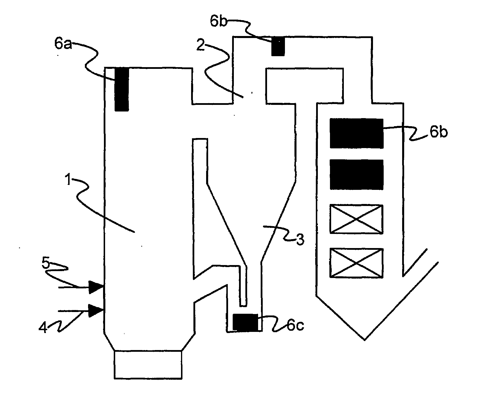
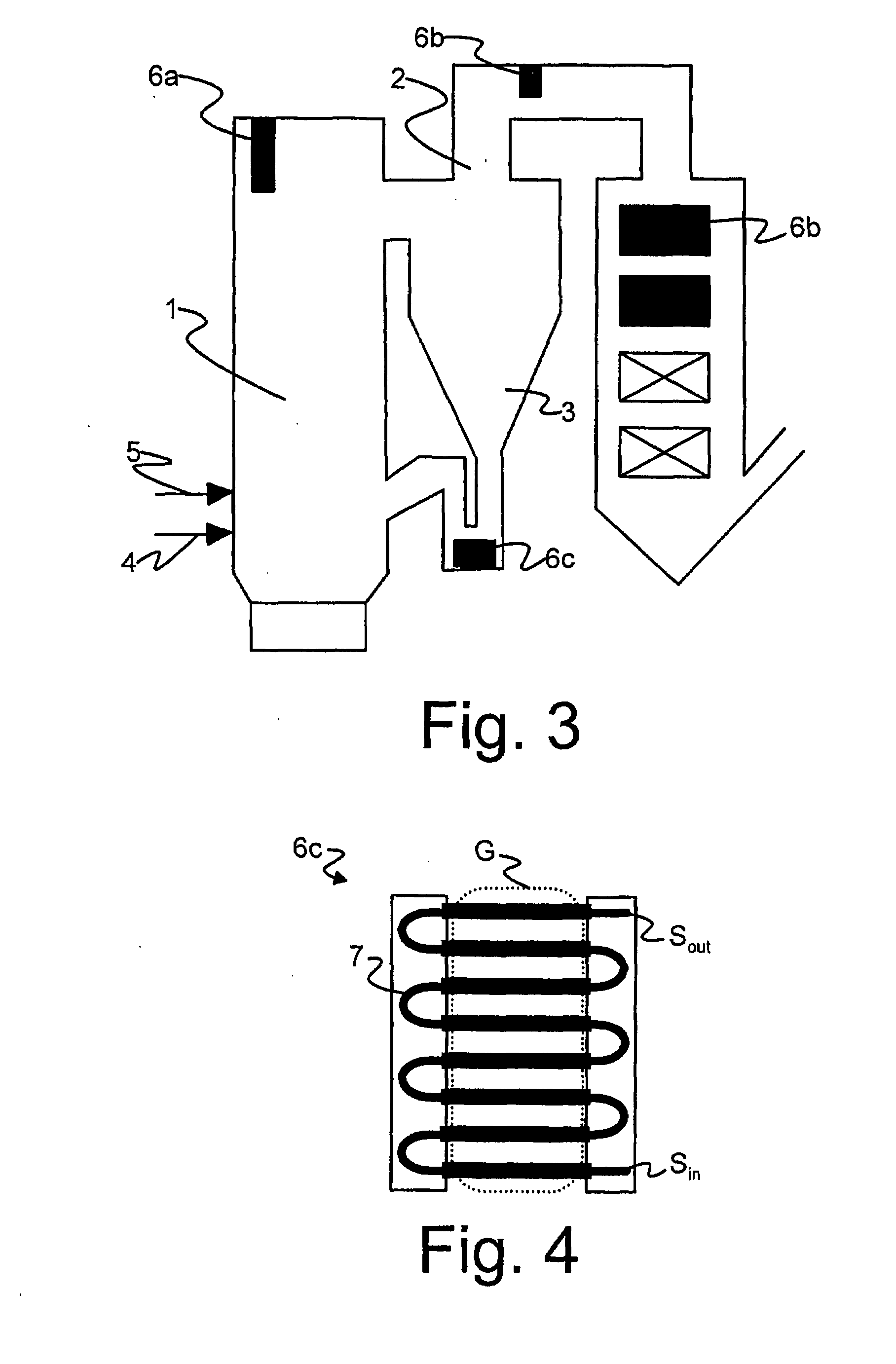
[0033]FIG. 3 shows in principle the structure of a circulating fluidized bed boiler. The boiler comprises a furnace 1, flue gas channels 2 and a cyclone 3, where the flue gases formed in the combustion can flow. In addition, FIG. 3 shows fuel supply 4 and combustion air supply 5, which are connected to the furnace 1, which may be on several layers. Flue gas cleaning systems are not shown in the figure.

[0034]In addition, the boiler comprises one of more superheaters 6a, 6b, 6c. The type of the superheater may be, for example, a radiant superheater 6a in the furnace, a superheater 6b in the flue gas channel, or a loopseal superheater 6c placed after the cyclone. In the following, the invention is described using the loopseal superheater 6c as an example, which is referred to as the superheater. It is, however, possible to apply the same principle for other superheaters 6a, 6b, 6c as well.

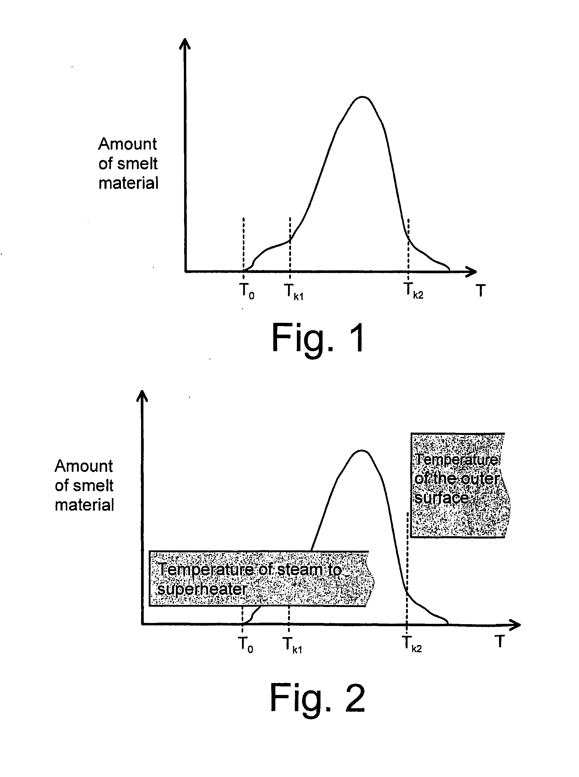
[0035]FIG. 4 shows the principle structure of the superheater 6c according to the invention. The s...


PUM


Abstract

A method for reducing corrosion of a superheater of a steam boiler. The superheater includes a superheater piping. The superheating piping includes a steam pipe where the steam to be superheated is directed. The steam pipe is separated by a protective shell having a surface settling in the flue gas space has a temperature that rises above an upper critical temperature, above which temperature in the flue gas space the compounds from the fuel are substantially in a gaseous form. A superheater of a steam boiler and a circulating fluidized bed boiler.

Description

FIELD OF THE INVENTION[0001]The invention relates to a method for reducing corrosion of a superheater of a steam boiler according to the preamble of the appended claim 1. The invention also relates to a superheater of a steam boiler according to the preamble of the appended claim 5, as well as a circulating fluidized bed boiler according to the preamble of the appended claim 9.BACKGROUND OF THE INVENTION[0002]The invention relates to the structure of a superheater of a steam boiler. Superheaters of steam boilers are typically placed in a flue gas flow and in circulating fluidized bed boilers (CFB-boiler) superheaters or a part of the superheaters can be placed below the cyclone, in a so-called loopseal (sand seal). The Increase of the superheating temperature and the heat-to-power ratio of the plant are for their part limited by superheater corrosion. The corrosion mechanism varies depending on combustion, structure and most of all the chemical composition of ash and combustion gase...

Claims


Application Information

Patent Timeline
IPC IPC(8): F22G7/14F28D13/00F22B31/00F22B37/10F22G3/00
CPCF22B31/0084F22G3/008F22B37/107
Inventor PETANEN, PERTTIMAKELA, KARIKUUKKANEN, KARIKOKKO, ARI
Owner VALMET TECH OY
Learn More