R-t-b based sintered magnet

a sintered magnet and r-t-b technology, applied in the field of r-t-b based sintered magnets, can solve the problems of increasing the requirements of magnetic materials, reducing the significant variation, and reducing the effect of ferromagnetism, so as to reduce the increase coercivity, and reduce the effect of deterioration of magnetic properties

Active Publication Date: 2010-01-07
HITACHI METALS LTD
View PDF3 Cites 2 Cited by
  • Summary
  • Abstract
  • Description
  • Claims
  • Application Information

AI Technical Summary

Benefits of technology

[0026]If Al is added to an R-T-B based sintered magnet, the magnet can have increased coercivity but may have some of its magnetic properties deteriorated in terms of the Curie temperature and saturation magnetization, for example. However, by substituting Mn for a certain percentage of its T ingredient, such deterioration in magnetic properties can be minimized. That is to say, by adding very small amounts of Mn and Al, the coercivity can be increased with the deterioration in magnetic properties minimized. Besides, the loop squareness of the demagnetization curve is also improved.

Problems solved by technology

And their requirements are becoming increasingly severe nowadays.
One of the old drawbacks of R-T-B based magnets is their relative low Curie temperature of approximately 300° C., at which their ferromagnetism is lost.
However, none of these measures will be effective enough to reduce the significant variation in coercivity with the temperature.
However, those heavy rare-earth elements such as Dy and Tb are among the rarest and most expensive ones of all rare-earth elements.
For that reason, if a lot of such heavy rare-earth elements should be used, then the price of the magnets would rise.
In addition, as the applications of such R-T-B based sintered magnet have been rapidly expanding these days, resource-related restrictions on those heavy rare-earth elements have become an issue these days because those rare elements are available only in very limited quantities and in very narrow areas.
That is why if the amount of such an additive were increased, the Curie temperature and magnetization of the main phase would decrease, which is a problem.
Furthermore, the additive elements such as Ti, V, Cr, Zr, Nb, Mo, Hf and W disclosed in Patent Document No. 5, for example, hinder the growth of crystal grains during the sintering process and reduce the size of the resultant metallurgical structure of the sintered body, thus contributing to increasing the coercivity.
According to any of the other methods mentioned above, however, a significant decrease in the magnetic flux density of the magnet is inevitable.

Method used


Image

  • R-t-b based sintered magnet
  • R-t-b based sintered magnet
  • R-t-b based sintered magnet

Examples


example 1

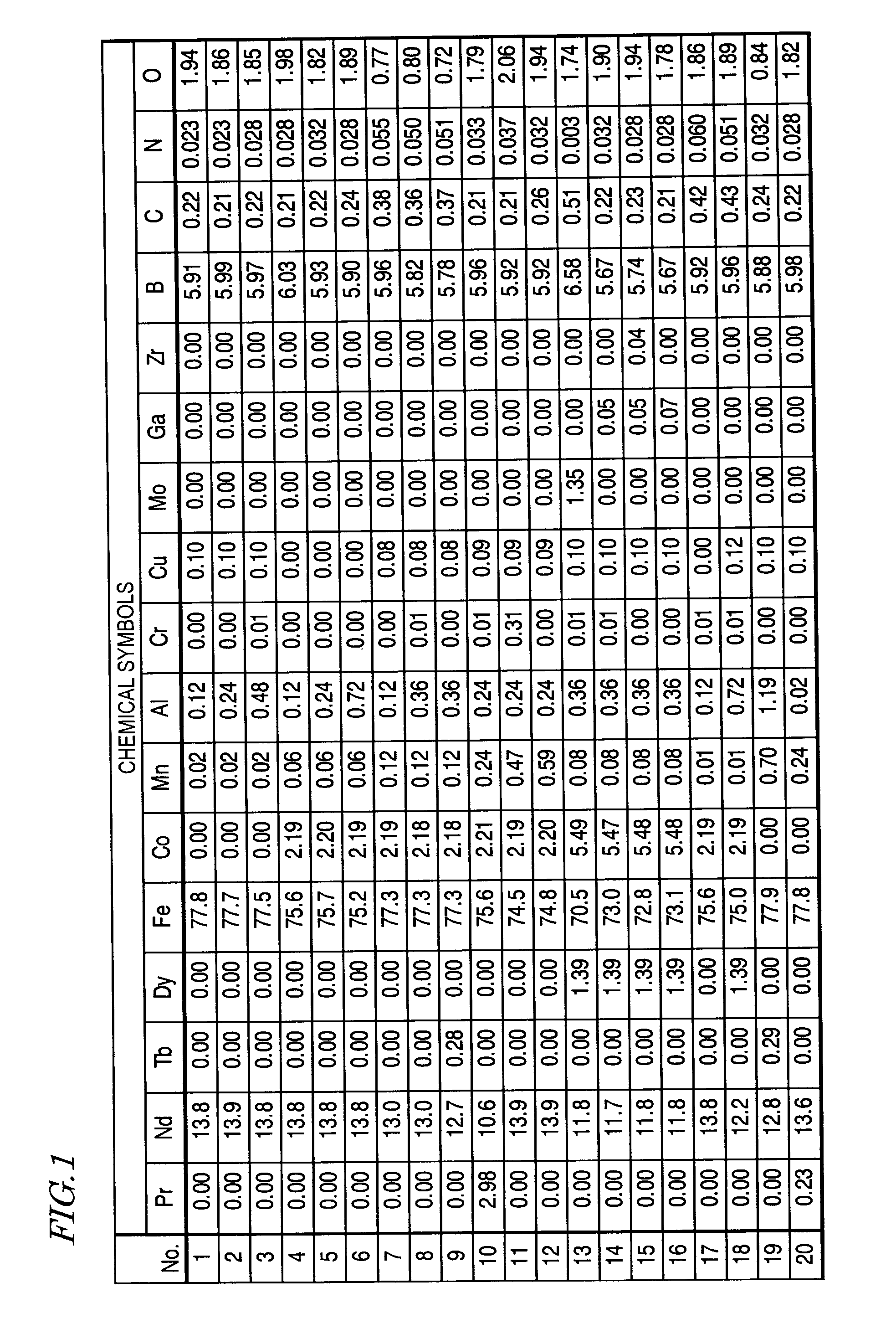
[0080]An alloy with an objective composition was prepared by mixing together Pr and Nd with a purity of 99.5% or more, Tb and Dy with a purity of 99.9% or more, electrolytic iron, and low-carbon ferroboron alloy together with the other objective elements added in the form of pure metals or alloys with Fe. The alloy was then melted and cast by a strip casting process, thereby obtaining a plate-like alloy with a thickness of 0.3 mm to 0.4 mm.

[0081]This material alloy was subjected to a hydrogen decrepitation process within a hydrogen atmosphere with an increased pressure, heated to 600° C. in a vacuum, cooled and then classified with a sieve, thereby obtaining a coarse alloy powder with a mean particle size of 425 μm or less. Then, zinc stearate was added to, and mixed with, this coarse powder so as to account for 0.05 mass % of the powder.

[0082]Next, the coarse alloy powder was subjected to a dry pulverization process using a jet mill machine in a nitrogen gas flow, thereby obtaining...

example 2

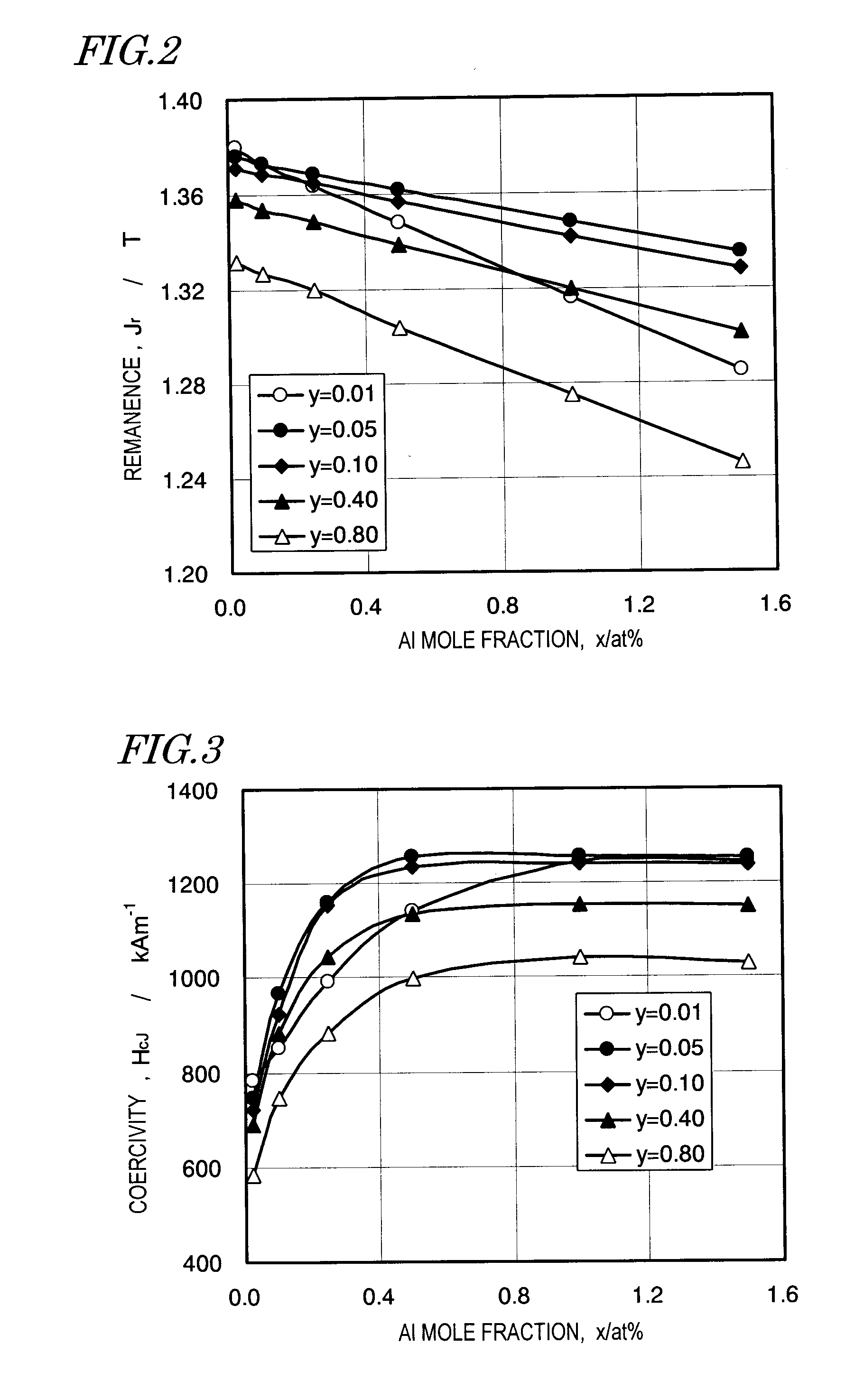
[0089]Magnets, of which the compositions were represented by Nd13.0Dy0.7Feba1.Co2.2Cu0.1B5.9AlxMny (where subscripts are atomic percentages), had their remanence Jr and coercivity HcJ measured at room temperature with y set to be 0.01, 0.05, 0.10, 0.40 and 0.80 and with the mole fraction x of Al varied. The results are shown in FIGS. 2 and 3, respectively. The curves associated with y=0.01 provide data about a comparative example. In this specific example, the content of oxygen was 1.8 at %, the contents of carbon and nitrogen were 0.4 at % or less and 0.1 at % or less, respectively, and the contents of other inevitable impurities such as Si, Ca, La and Ce were 0.1 at % or less. The magnets of this Example 2 were produced by the same method as that adopted for Example 1.

[0090]As shown in FIG. 2, when y=0.05, the decrease in remanence Jr with the increase in the amount of Al added was less significant than the situation where y=0.01. This result was obtained probably due to a reducti...

example 3

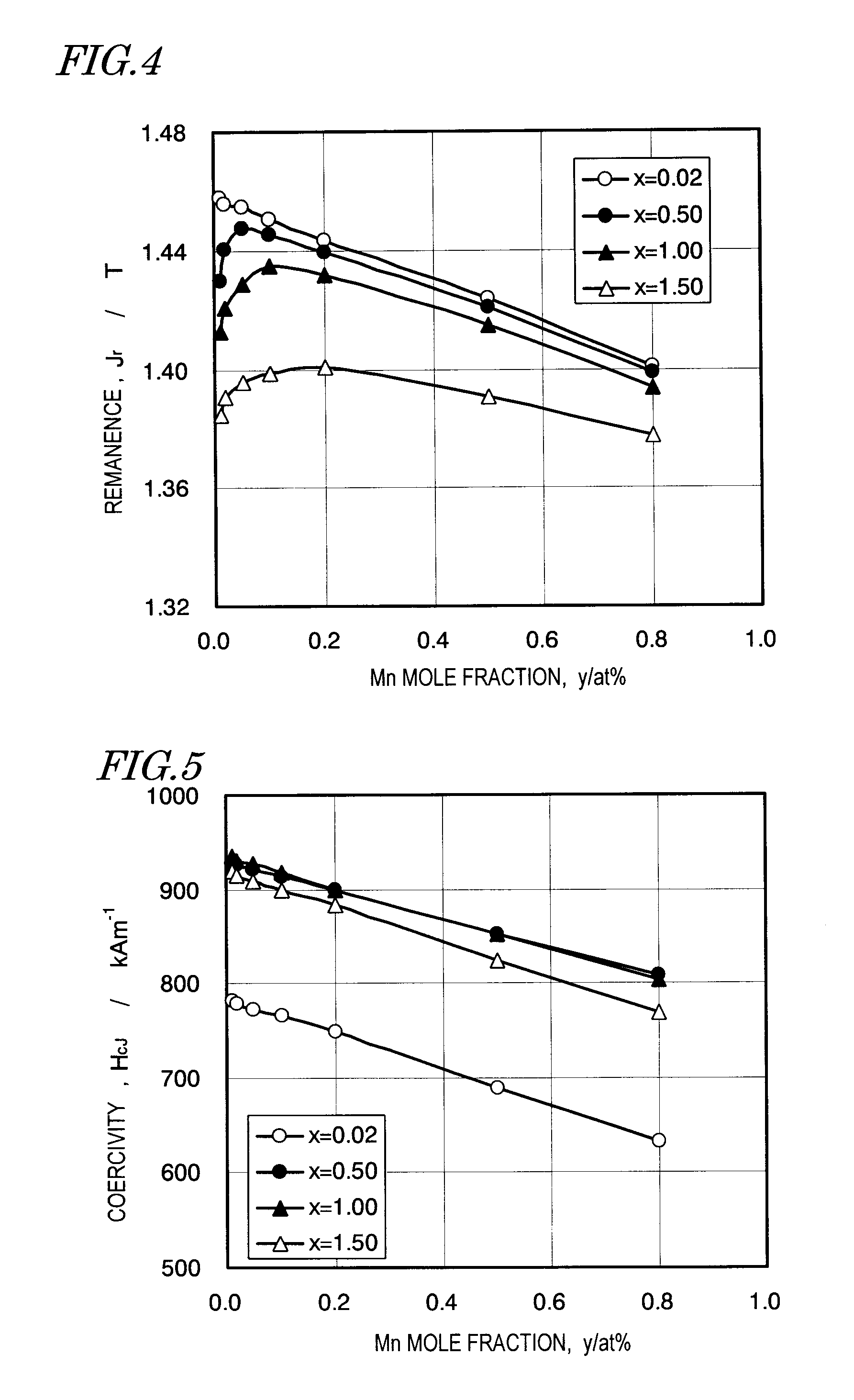
[0092]Magnets, of which the compositions were represented by Nd12.8Feba1.Co2.2Cu0.1Ga0.05B5.7AlxMny (where subscripts are atomic percentages), had their remanence Jr and coercivity HcJ measured at room temperature with x set to be 0.02, 0.50, 1.00 and 1.50 and with the mole fraction y of Mn varied. The results are shown in FIGS. 4 and 5, respectively. The curves associated with x=0.02 and 1.50 provide data about comparative examples. In this specific example, the content of oxygen was 1.8 at %, the contents of carbon and nitrogen were 0.4 at % or less and 0.1 at % or less, respectively, and the contents of other inevitable impurities such as Si, Ca, La and Ce were 0.1 at % or less. The magnets of this Example 3 were produced by the same method as that adopted for Example 1.

[0093]According to the results shown in FIG. 4, if Al was added so as to account for a mole fraction x of 0.5 at % without adding Mn, the remanence Jr decreased significantly. However, when y=0.05, the difference ...


PUM

PropertyMeasurementUnit
Curie temperatureaaaaaaaaaa
temperaturesaaaaaaaaaa
D50 particle sizeaaaaaaaaaa

Abstract

An R-T-B based sintered magnet according to the present invention has a composition comprising: 12 at % to 15 at % of a rare-earth element R; 5.0 at % to 8.0 at % of boron B; 0.1 at % to at % of Al; 0.02 at % to less than 0.2 at % of Mn; and a transition metal T as the balance. The rare-earth element R is at least one element selected from the rare-earth elements, including Y (yttrium), and includes at least one of Nd and Pr. The transition element T includes Fe as its main element.

Description

[0001]This application is a continuation application U.S. application Ser. No. 12 / 132,689 filed on Jun. 4, 2008, which is a continuation application of International Application No. PCT / JP2007 / 059373, with an international filing date of May 2, 2007.BACKGROUND OF THE INVENTION[0002]1. Field of the Invention[0003]The present invention relates to an R-T-B (rare-earth-iron-boron) based sintered magnet.[0004]2. Description of the Related Art[0005]R-T-B based sintered magnets have so good magnetic properties as to find a wide variety of applications including various types of motors and actuators and are now one of indispensable materials for the electronics industry. Also, their applications have been appreciably broadened to keep up with the recent trend toward energy saving.[0006]Lately, however, those motors and actuators are more and more often required to exhibit much higher performance than conventional ones in their rapidly expanding applications including motors for driving, or ...

Claims


Application Information

Patent Timeline
Patent Type & Authority Applications(United States)
IPC IPC(8): C22C38/04C22C38/00C22C38/10C22C38/06C22C38/16
CPCC22C38/005H01F1/0577C22C38/06C22C38/04C22C38/10
Inventor TOMIZAWA, HIROYUKI
Owner HITACHI METALS LTD
Why Eureka
Try Eureka