Modified inorganinc materials

a technology of inorganic materials and modified materials, applied in the field of modified inorganic materials, can solve the problems of large-scale delivery of agrochemicals with great inefficiencies and limited development at the lower expense end, and achieve the effect of safe handling and storag

Inactive Publication Date: 2010-01-07
THE UNIV OF SYDNEY
View PDF3 Cites 3 Cited by
  • Summary
  • Abstract
  • Description
  • Claims
  • Application Information

AI Technical Summary

Benefits of technology

[0027]The conditioning employed may then be targeted or tuned to the specific active and its application. For example, the affinity of the tubular clay material for the active can be altered in a manner such that the material can act to release active in a controllable manner and/or to store or entrap active. In other words, the application

Problems solved by technology

Developments at the lower expense end have been limited.
As a result, large-

Method used


Image

  • Modified inorganinc materials
  • Modified inorganinc materials
  • Modified inorganinc materials

Examples


example 1

[0057]Halloysite was obtained from a test site in Camel Lake, South Australia and from New Zealand China Clay Ltd of grade G. The characteristics of these halloysites were determined and are as shown in Table 1:

TypeHalloysite G (HG)Camel Lake (Cla1)Length (μm)0.50.85External Diameter (nm)3060Internal Diameter (nm)2324.5Calculated Aspect Ratio6.00 × 10 − 27.06 × 10 − 2Specific Surface Area (m2 / g)65.125.3Lumen Volume (cm3 / g)0.160.075

example 2

Clay Conditioning

[0058]Three methods were used to modify (condition) the clays of Example 1, in this case, the halloysite tubes:

[0059](a) Surfactant Modification:[0060]Halloysite (5.0 g) was refluxed (30 min, 80° C.) with water (500 ml). HDTMA (8 ml, HDTMA aqueous solution 25% grade in H2O, Fluka) was added and the suspension refluxed (1 hr, 80° C.), then allowed to cool overnight with stirring. The suspension was filtered and washed with water until the counter ion was not detected in the filtrate by one drop of AgNO3 (0.1 M. The ratio (w / w) of clay to HDTMA was also varied to control the extent of modification. The ratios used were 1:1, 2:3, 1:5, 1.10 and 1:20.

[0061](b) Alcohol Modification:[0062]Halloysite (dried and ground) was placed into a vacuum tube and covered with 1-octanol. The mixture was sired and heated to 194° C. using microwave irradiation. A vacuum was applied to the mixture until the appearance of “fizzing” stopped (i.e. the air trapped in the tubes had escaped). A...

example 3

Loading of Conditioned Clay

[0066]For actives of low melting point, the “melt method” of loading was used. For actives of high melting point, the “solution method” was used.

Melt Method:

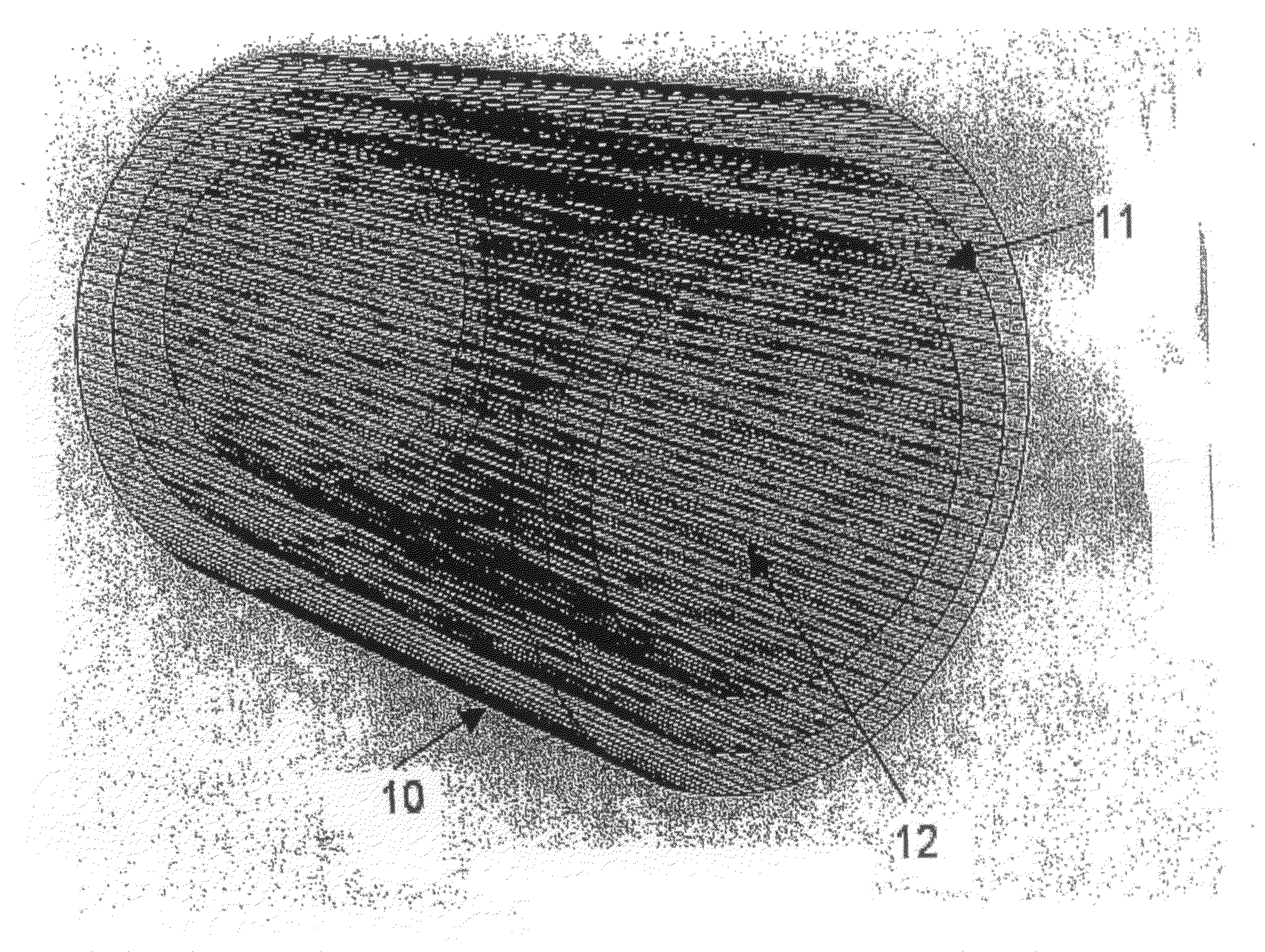
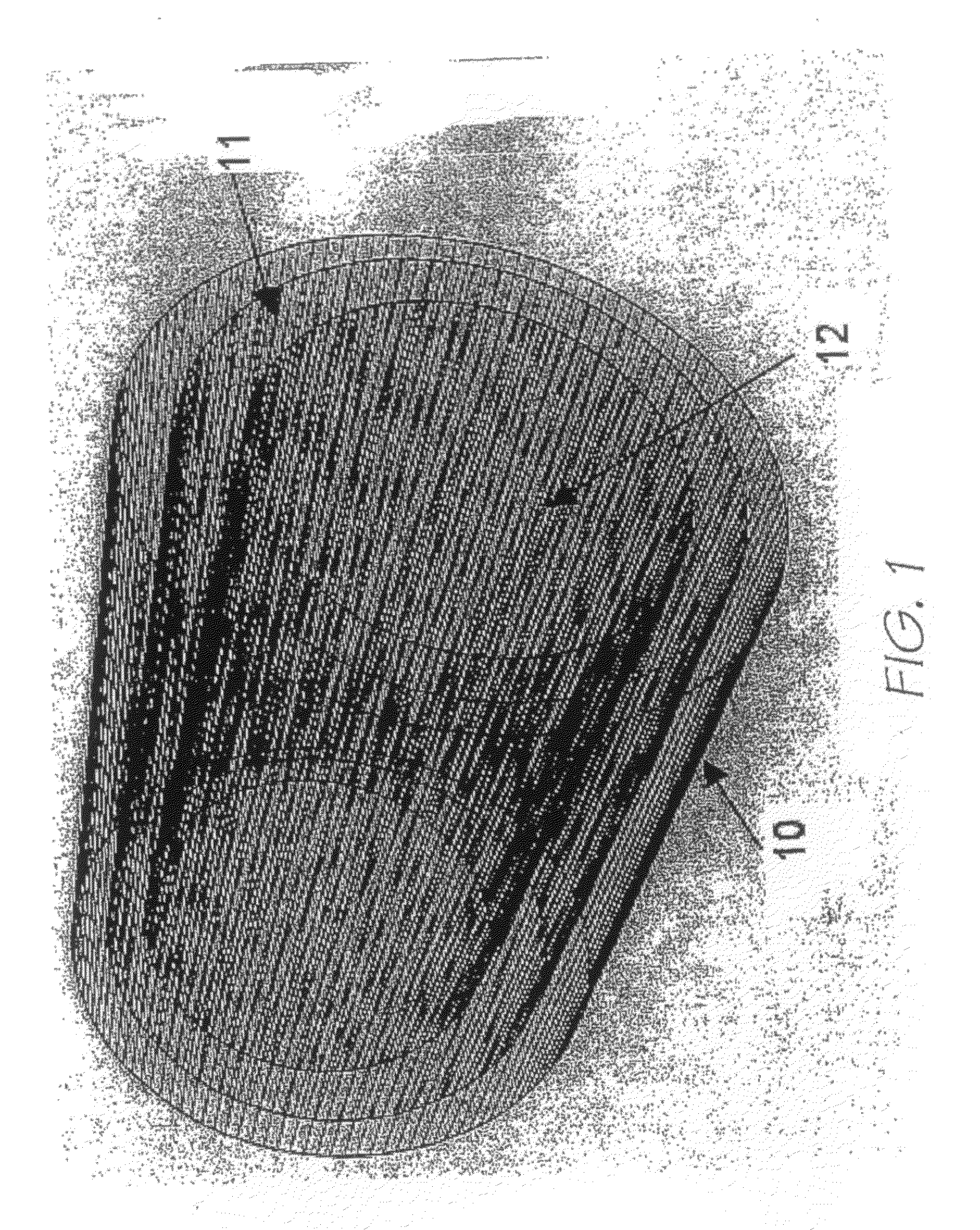
[0067]Dried modified clay was ground in a 1:1 (w / w) ratio with the active to be loaded. The mix was heated to above the melting point of the active for 5 hours. The active entered the lumen 12 via capillary action.

Solution Method:

[0068]A solvent was selected in which the active was highly soluble. For example, to load the compound benzophenone, acetone was used. A saturated solution of active was mixed with dried, ground modified clay by stirring, followed by exposure to an ultrasonic bath (20 min). The mix was placed in a Schlenk tube and subjected to three vacuum cycles, and was then centrifuged. After removal of supernatant solution, the loaded clay was dried at 90° C. for 24 hours.

[0069]The modes of delivery of loaded modified tubes differed between applications. This example also outlined a method...


PUM

PropertyMeasurementUnit
Temperatureaaaaaaaaaa

Abstract

A method of conditioning a tubular clay material to enable its loading with an active, the method comprising the step of exposing the tubular clay material to a chemical agent in a manner such that the agent sorbs to a surface of the clay material that is internal of the tube, the chemical agent being selected such that, when the agent is sorbed to the clay material internal surface, the affinity of the tubular clay material for the active is altered.

Description

TECHNICAL FIELD[0001]Methods for modifying tubular shaped inorganic materials are disclosed, as are the resultant materials themselves. More particularly the method involves the conditioning of a tubular clay material to alter its affinity for an active chemical (hereafter “active”).BACKGROUND ART[0002]Global demand for inexpensive technologies that allow the controlled release of actives such as herbicides, pesticides and fertilizers is increasing. In particular, there is a demand for controlled release hosts (or carriers) that are inexpensive, have higher weight-per-weight loadings, are environmentally friendly, have release rates that can be controlled to range from days to months, and that can act as hosts for a range of actives that have a biological effect.[0003]Attempts to meet these criteria at the higher expense end of the market have involved micro-encapsulation of actives such as agrochemicals into polymer-based granules and spheroids. Examples include products marketed u...

Claims


Application Information

Patent Timeline
IPC IPC(8): A01N25/08B05D7/22C05D9/00A61K9/00A61K8/02C11D17/00C02F5/08C09K15/00A01N37/18A01N33/18A01P1/00A01P13/00
CPCA01N25/08
Inventor KEPERT, CAMERON JOHNGREEN, MALCOLM EDWARD ROLANDANTILL, SARAH JANE
Owner THE UNIV OF SYDNEY
Why Eureka
Try Eureka