
Apparatus and Methods for Determining Overlay and Uses of Same

a technology of semiconductors and overlays, applied in semiconductor/solid-state device testing/measurement, instruments, total factory control, etc., can solve the problems of high-complex fabrication techniques of integrating circuits, device defects must be detected within special test structures or targets, and the manufacturing process is highly complex. , to achieve the effect of accurately predicting device performance and yield, improving manufacturing process, and accurately correcting

Active Publication Date: 2010-01-07
KLA TENCOR TECH CORP
View PDF98 Cites 58 Cited by
  • Summary
  • Abstract
  • Description
  • Claims
  • Application Information

AI Technical Summary

Benefits of technology

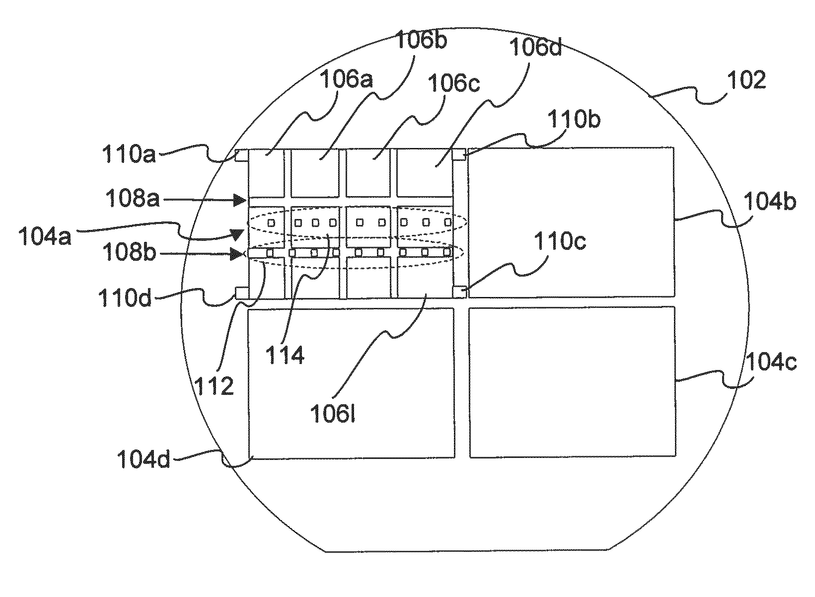
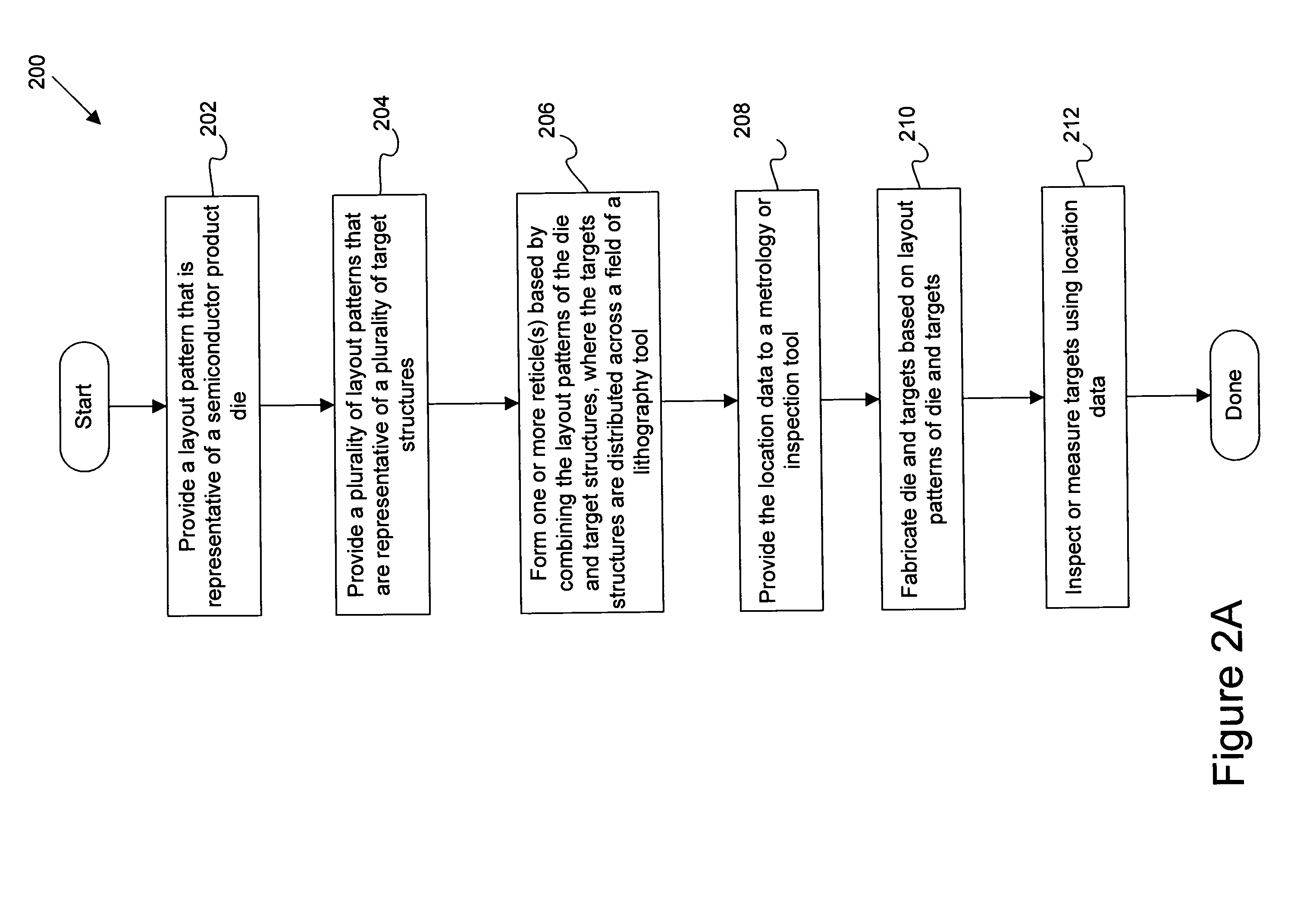
[0008]Accordingly, apparatus and methods are provided for determining overlay error or pattern placement error (PPE) across the field of a lithography tool which is used to pattern a sample, such as a semiconductor wafer or device. This determination is performed in-line on the product wafer or device. That is, the targets on which overlay or PPE measurements are performed are provided on the product wafer or device itself. The targets are either distributed across the field by placing the targets within the active area or by distributing the targets along the streets (the strips or scribe areas) which are between the dies of a field. The resulting overlay or PPE that is obtained from targets distributed across the field may then be used in a number of ways to improve the fabrication process for producing the sample. For instance, the resulting overlay or PPE may be used to more accurately predict device performance and yield, more accurately correct a deviating photolithography scanning tool, or determine wafer lot disposition.

Problems solved by technology

Generally, the industry of semiconductor manufacturing involves highly complex techniques for fabricating integrating circuits using semiconductor materials which are layered and patterned onto a substrate, such as silicon.
Due to the large scale of circuit integration and the decreasing size of semiconductor devices, the device must be defect free prior to shipment of the device to the end users or customers.
Typically, defects are detected within special test structures or targets, rather than the active device or die itself.
It has been undesirable to utilize active area space for nonfunctioning structures because engineers are constantly striving to maximize active feature density.
Unfortunately, a test structure positioned in the four corners of the exposure tool field or the scribe line does not best represent product function or typical variations across the field of the lithography (or exposure) tool.
Accordingly, defects captured or measured within the targets may not be a good indicator of defects within the product area or die itself.
In a specific case, the lithography tool usually contains aberrations in its lens system which result in feature misalignments or pattern placement errors across the field.

Method used


Image

  • Apparatus and Methods for Determining Overlay and Uses of Same
  • Apparatus and Methods for Determining Overlay and Uses of Same
  • Apparatus and Methods for Determining Overlay and Uses of Same

Examples


Embodiment Construction

[0032]Reference will now be made in detail to a specific embodiment of the invention. An example of this embodiment is illustrated in the accompanying drawings. While the invention will be described in conjunction with this specific embodiment, it will be understood that it is not intended to limit the invention to one embodiment. On the contrary, it is intended to cover alternatives, modifications, and equivalents as may be included within the spirit and scope of the invention as defined by the appended claims. In the following description, numerous specific details are set forth in order to provide a thorough understanding of the present invention. The present invention may be practiced without some or all of these specific details. In other instances, well known process operations have not been described in detail in order not to unnecessarily obscure the present invention.

[0033]Introduction

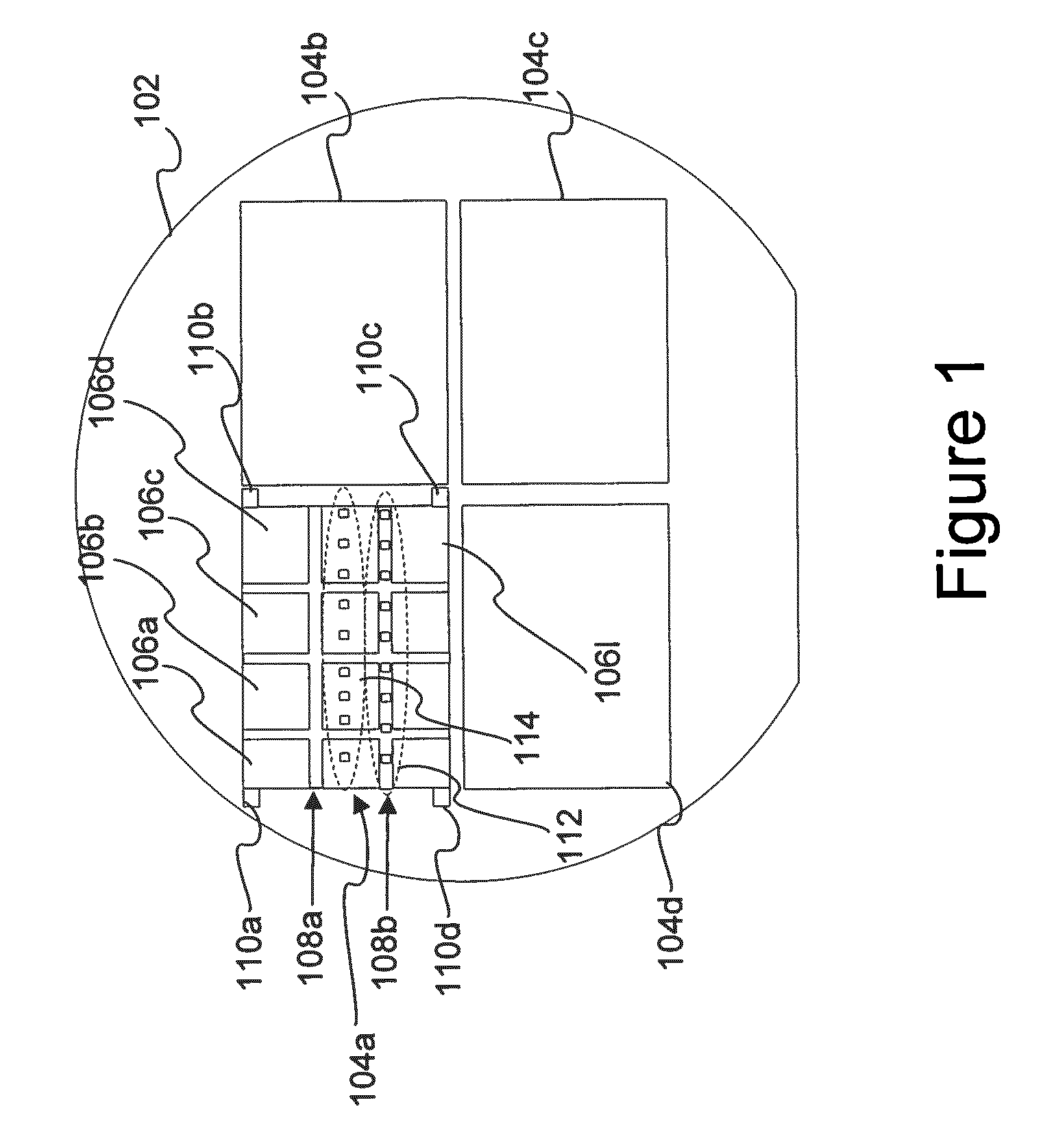
[0034]FIG. 1 is a diagrammatic top view of a wafer 102 having a plurality of field areas 1...


PUM


Abstract

Disclosed are techniques and apparatus are provided for determining overlay error or pattern placement error (PPE) across the field of a scanner which is used to pattern a sample, such as a semiconductor wafer or device. This determination is performed in-line on the product wafer or device. That is, the targets on which overlay or PPE measurements are performed are provided on the product wafer or device itself. The targets are either distributed across the field by placing the targets within the active area or by distributing the targets along the streets (the strips or scribe areas) which are between the dies of a field. The resulting overlay or PPE that is obtained from targets distributed across the field may then be used in a number of ways to improve the fabrication process for producing the sample. For instance, the resulting overlay or PPE may be used to more accurately predict device performance and yield, more accurately correct a deviating photolithography scanning tool, or determine wafer lot disposition.

Description

CROSS REFERENCE TO RELATED PATENT APPLICATION[0001]This is a divisional of co-pending U.S. patent application Ser. No. 10 / 950,172, filed 23 Sep. 2004 by Mark Ghinovker et al., entitled “APPARATUS AND METHODS FOR DETERMINING OVERLAY AND USES OF SAME”, which claims priority of (i) U.S. Provisional Patent Application No. 60 / 506,281, filed 26 Sep. 2003 by Michael E. Adel, et al., (ii) U.S. Provisional Patent Application No. 60 / 546,546, filed 20 Feb. 2004 by Michael E. Adel, et al, and (iii) U.S. patent application Ser. No. 10 / 858,836, filed Jun. 1, 2004 now U.S. Pat. No. 7,346,878, issued 18 Mar. 2008, by Avi Cohen, et al., which application claims priority of U.S. Provisional Application No. 60 / 484,627, filed Jul. 2, 2003 by Avi Cohen, et al. These applications and patent are incorporated herein by reference in their entirety for all purposes.BACKGROUND OF THE INVENTION[0002]The present invention relates generally to the field of semiconductor overlay metrology. More specifically, it r...

Claims


Application Information

Patent Timeline
Patent Type & Authority Applications(United States)
IPC IPC(8): G06F17/50
CPCG03F7/70633G06F2217/12G06F17/5068G06F30/39G06F2119/18Y02P90/02
Inventor GHINOVKER, MARKADEL, MICHAEL E.POPLAWSKI, JORGESELIGSON, JOEL L.
Owner KLA TENCOR TECH CORP
Learn More