Wire slicing system

a slicing system and wire technology, applied in the direction of saw chains, manufacturing tools, metal working apparatuses, etc., can solve the problems of long machining time, slow production rate, long machining time, etc., to achieve fast cutting rate, improve quality, and facilitate the slicing process versatility

Inactive Publication Date: 2010-01-14
SAINT GOBAIN ABRASIVES INC +1
View PDF22 Cites 71 Cited by
  • Summary
  • Abstract
  • Description
  • Claims
  • Application Information

AI Technical Summary

Benefits of technology

[0013]The slicing system, subsystems and operations described herein are particularly well suited in wafering or cropping operations and can be employed to cut ceramics, in particular hard and brittle ceramics, metals, organics and other workpieces. When compared to existing slicing machines, specific implementations of the invention can provide fast cutting rates and cuts of improved quality. For instance, a fixed diamond abrasive wire slicing machine according to preferred embodiments of the invention can reach a wire speed of 15 m/s and can have a tension range of up to 50N.
[0014]Advantageously, implementations of the invention provide unique handling of the workpiece which allows for versatility in the slicing process. An ingot can be moved up and down, forward and backward as well as rotated or rocked during slicing. By practicing aspects of the invention, wafers can be sl

Problems solved by technology

The demand for high quality, ultra-thin wafers cut from blocks or ingots of hard, brittle crystals and ceramics continues to challenge cutting machine and abrasive manufacturers.
Several disadvantages are associated with conventional methods of cutting thin wafers from crystal blocks.
While the quality of ID-sawed wafers is good, this one-piece-at-a-time approach translates into long machining times and slow production rates.
Furthermore, sizes of work pieces that can be handled with ID saws often are limited.
While MWS enables

Method used


Image

  • Wire slicing system
  • Wire slicing system
  • Wire slicing system

Examples


Embodiment Construction

[0038]The above and other features of the invention including various details of construction and combinations of parts, and other advantages, will now be more particularly described with reference to the accompanying drawings and pointed out in the claims. It will be understood that the particular method and device embodying the invention are shown by way of illustration and not as a limitation of the invention. The principles and features of this invention may be employed in various and numerous embodiments without departing from the scope of the invention.

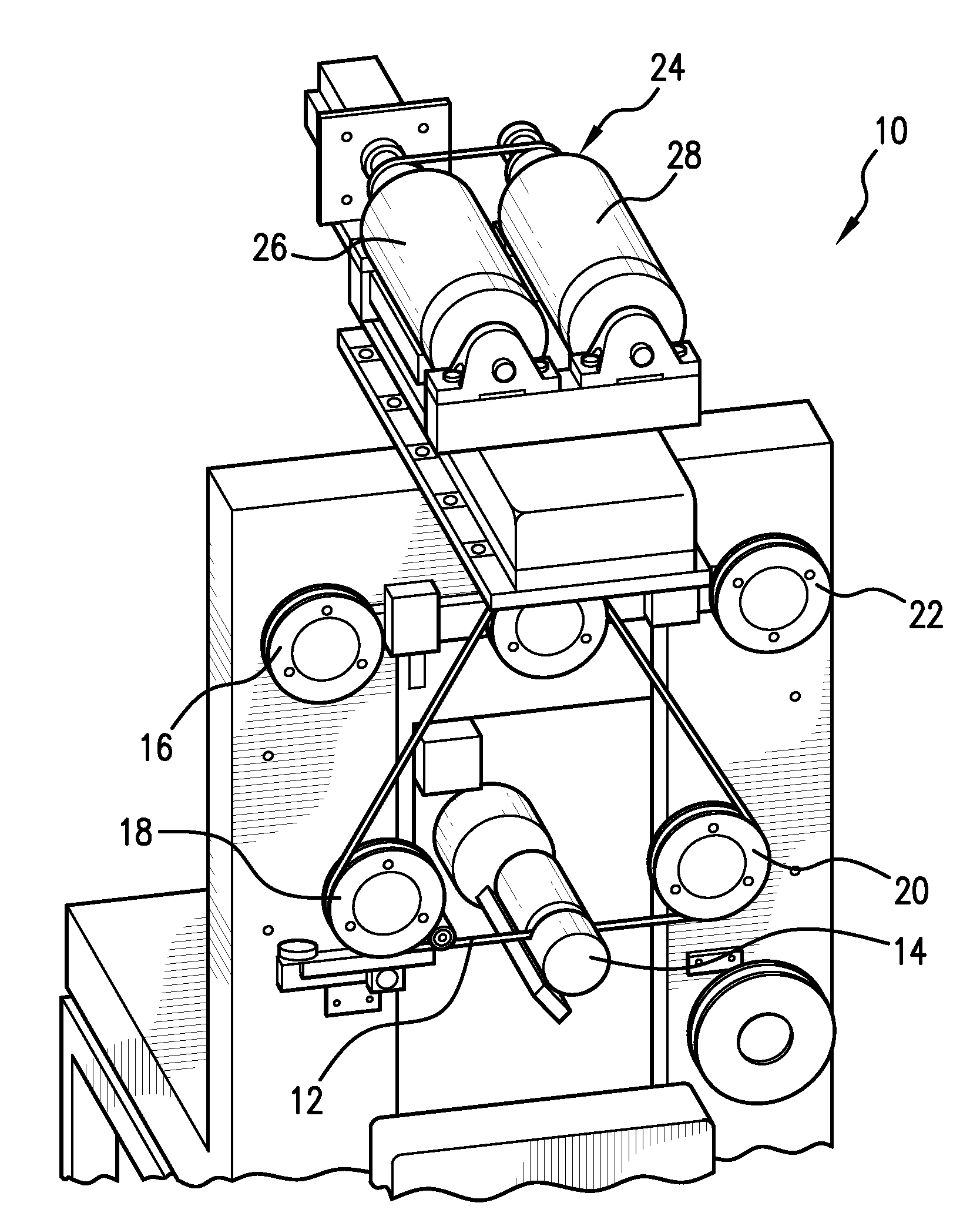
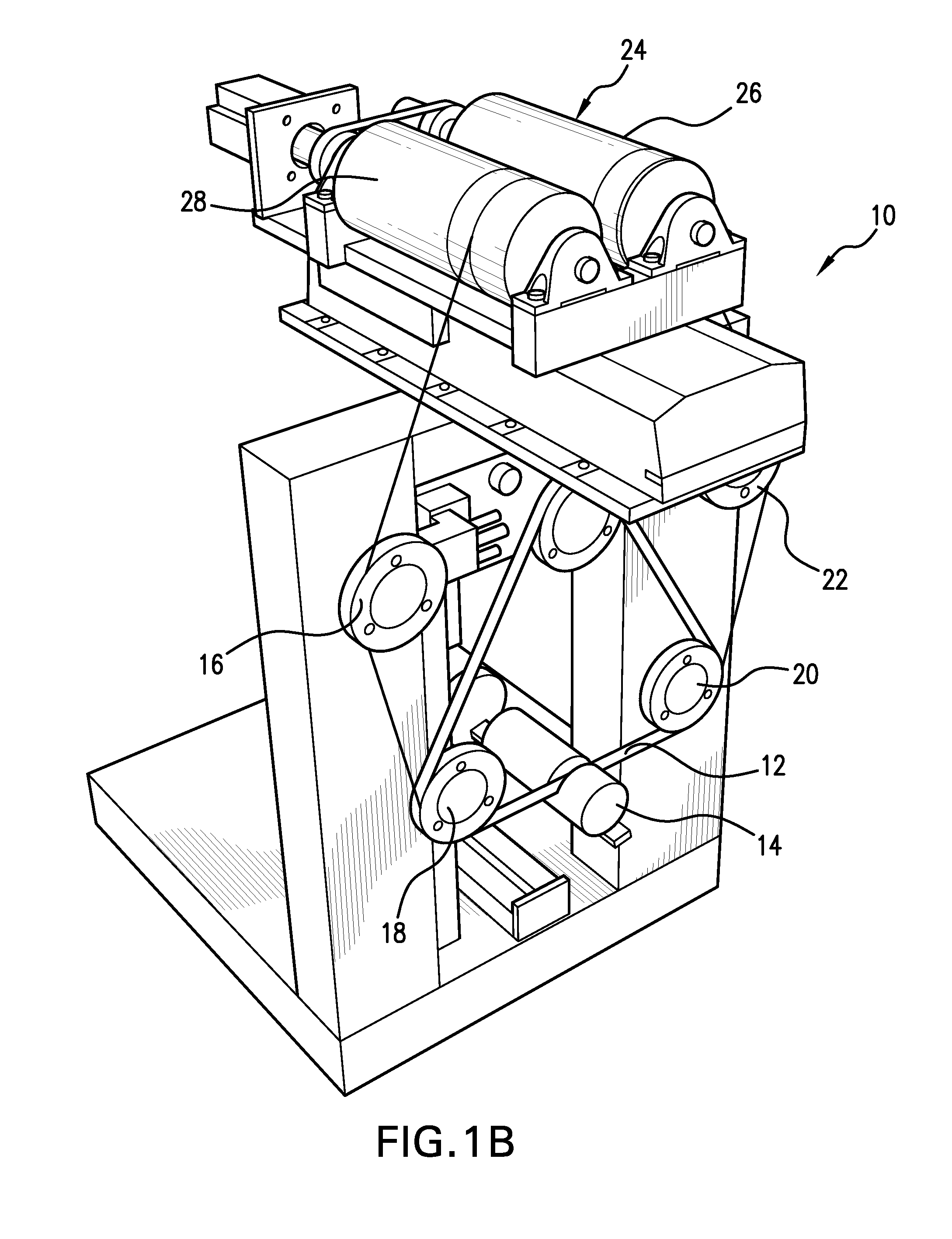
[0039]The invention generally relates to equipment and processes that can be employed during wire sawing, also referred to as wire slicing operations.

[0040]Wire slicing generally is carried out to cut or shape a workpiece and includes contacting the workpiece with at least one wire. In many implementations, the wire is a fixed abrasive wire in which abrasive grains or grits are bonded to a core made of materials such as stainles...


PUM

PropertyMeasurementUnit
Lengthaaaaaaaaaa
Angleaaaaaaaaaa
Abrasiveaaaaaaaaaa

Abstract

A wire slicing system and method for using it include one or more of the following features: arrangements and/or operations that relate to handling the wire; apparatus and methods that relate to wire tensioning; equipment and techniques for manipulating the workpiece; arrangements and/or operations designed for cooling and swarf (debris) removal; controls and/or automation that can be used in conjunction with these features.

Description

RELATED APPLICATIONS[0001]This application claims the benefit under 35 USC 119(e) of U.S. Provisional Application No. 61 / 079,928, filed on Jul. 11, 2008, which is incorporated herein by reference in its entirety.BACKGROUND OF THE INVENTION[0002]The demand for high quality, ultra-thin wafers cut from blocks or ingots of hard, brittle crystals and ceramics continues to challenge cutting machine and abrasive manufacturers. Traditionally, these wafers have been produced using annular (circular) sawing or multi-wire slicing (MWS) using loose diamond abrasive.[0003]Several disadvantages are associated with conventional methods of cutting thin wafers from crystal blocks. With annular sawing, also called “ID sawing”, the wafers are cut individually from the workpiece. While the quality of ID-sawed wafers is good, this one-piece-at-a-time approach translates into long machining times and slow production rates. Furthermore, sizes of work pieces that can be handled with ID saws often are limit...

Claims


Application Information

Patent Timeline
IPC IPC(8): B28D5/00B28D1/08B28D1/06
CPCB28D1/30B28D5/045B28D5/0088B28D5/0064Y10T83/9292
Inventor GLINSKI, LUKASZ A.GRAHAM, DAVIDLAMBERT, EDWARD L.SUBRAMANIAN, KRISHNAMOORTHY
Owner SAINT GOBAIN ABRASIVES INC
Why Eureka
Try Eureka