Device for feeding a charge including integrated energy storage

a technology of integrated energy storage and charging device, which is applied in the direction of ac network circuit arrangement, dc-dc conversion, dc-dc conversion, etc., can solve the problems of wasting a lot of energy, and affecting the reliability of the system

Inactive Publication Date: 2010-01-14
ECOLE POLYTECHNIQUE FEDERALE DE LAUSANNE (EPFL) +1
View PDF7 Cites 24 Cited by
  • Summary
  • Abstract
  • Description
  • Claims
  • Application Information

AI Technical Summary

Benefits of technology

[0013]In such an application, current flows in the converters, the magnet coils and other components results in energy losses that cause a slow discharge of the capacitive circuits from one power cycle to the next. To compensate this discharge, another aim of the invention is to propose a device for controlling and adjusting the operation of all the converters so that energy can be transferred from one converter to another while the delivered current is flowing, thus allowing the mean values of the voltages of the intermediate DC circuits to be maintained by transferring energy from one converter to another, in particular from a powered converter to an unpowered converter.

Problems solved by technology

The direct connection of such consumers to the electrical power grid can cause serious grid disturbances.
In addition, common energy supply devices are generally fitted with resistive energy dissipators that dissipate energy when the power flux is reversed, which obviously wastes a lot of energy.
The U.S. Pat. No. 5,638,263 describes a similar device in which each DC / DC converter is supplied via its own voltage rectifier, which leads to a system which is clearly more expensive and clearly less reliable.
In such an application, current flows in the converters, the magnet coils and other components results in energy losses that cause a slow discharge of the capacitive circuits from one power cycle to the next.

Method used


Image

  • Device for feeding a charge including integrated energy storage
  • Device for feeding a charge including integrated energy storage
  • Device for feeding a charge including integrated energy storage

Examples


first embodiment

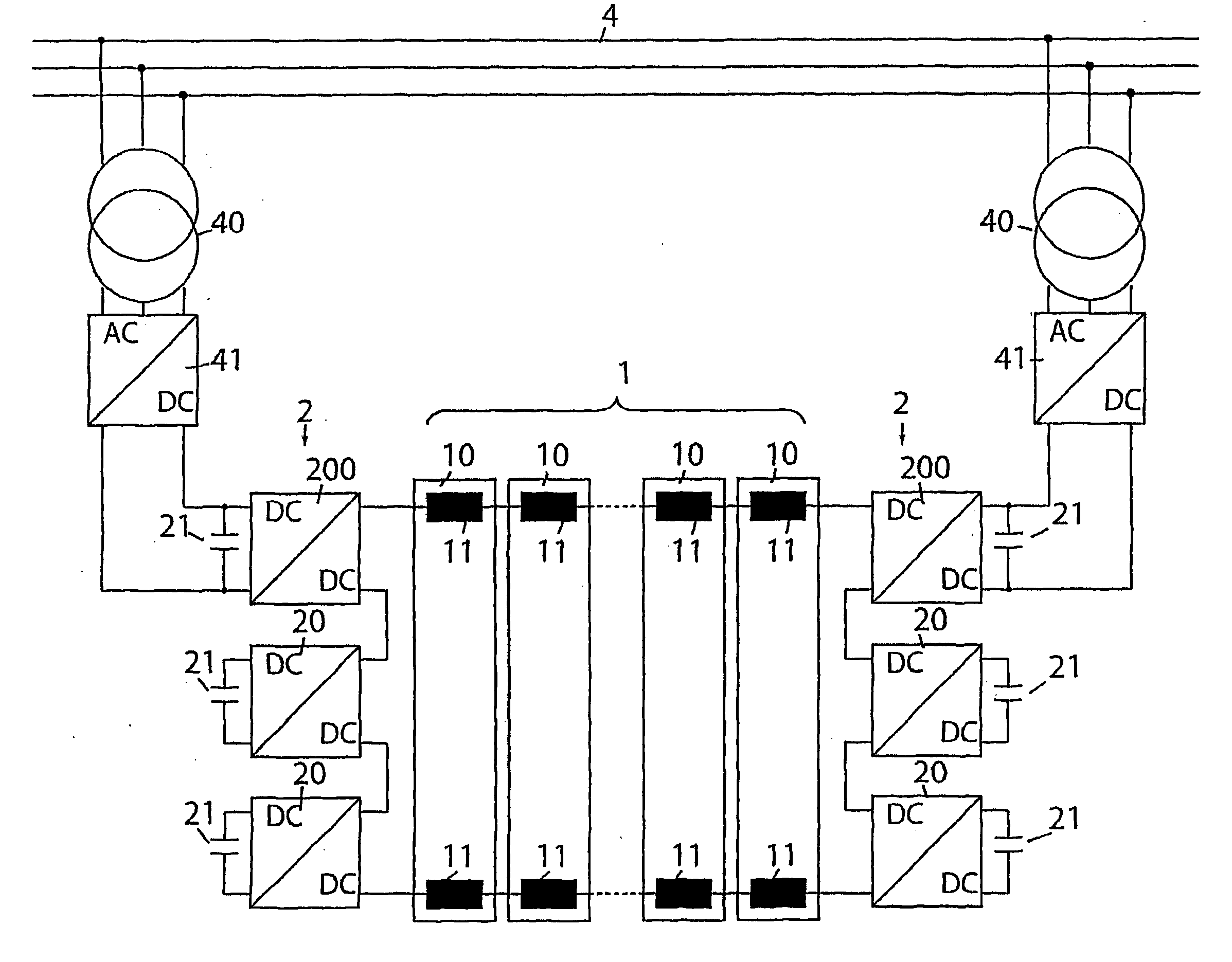
[0062]In a first embodiment, the rectifier cells 41 comprise a diode bridge 42, as shown in FIG. 14. In this embodiment, there is no control of the diode rectifiers 42 so the voltage at the terminals of the capacitors 21 of the DC / DC converter cells 200 cannot be modified. Therefore, such a device does not allow use of the energy stored in the capacitors 21, directly connected to the above-mentioned DC / DC converter cells 200, which are connected to the rectifier cells 41. A smoothing choke 43 is provided at the positive output of the bridge.

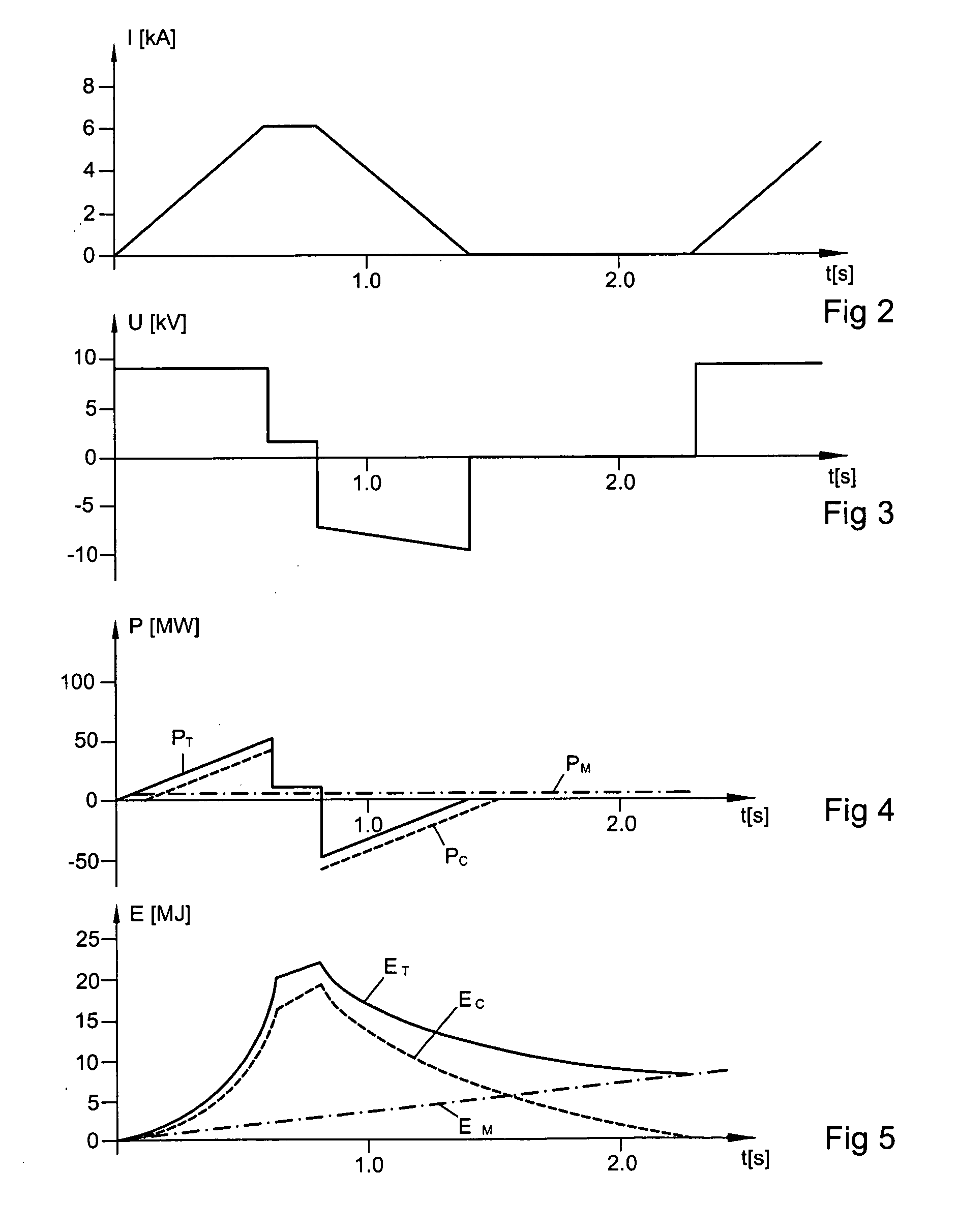
[0063]Variation of the output voltage of the rectifier cells 41 remains possible, given that the DC / DC converter cells 200 are operating according to the PWM principle, as described above. Thus, while the load current is being ramped up, there is zero energy contribution from the capacitors 21 of the DC / DC converter cells 200, directly supplied by the rectifier cells 41, namely the two cells 200 shown at the top of the diagram in FIG. 6, so the p...

second embodiment

[0065]In the second embodiment, the rectifier cells 41 are formed from a thyristor bridge 44, as shown in FIG. 15. In this embodiment, it thus becomes possible to vary the voltage at the terminals of the capacitors 21. To control the thyristor bridges, the ignition angle α of the thyristors 44 will be varied according to the voltage variation at the terminals of the capacitors 21. This variation of the voltage will allow the capacitors 21 to be discharged. In this case, the instantaneous power supplied by the thyristor rectifier cells 41 is not equal to the instantaneous power transmitted to the load. As for the previous embodiment, a smoothing choke 43 is provided at the positive output of the cell 41.

[0066]The use of thyristors in the rectifier cells 41, controlling the ignition angle α of the thyristors 44, entails a variation of the phase angle between the voltage and the alternating current at the input of the rectifier cells 41, thereby drawing reactive power from the primary ...

third embodiment

[0068]In a third embodiment, the rectifier cells 41 are formed from pulse rectifiers as shown in FIG. 16. In this case, the rectifier cell 41 includes a bridge assembly formed from GTO or IGCT-type thyristors 45, as shown on the left-hand side of the figure, or IGBT-type transistors 46, as shown on the right-hand side of the figure, it being understood that the bridge is formed from only semiconductor elements of one or the other type. Each of the above-mentioned semiconductor elements 45 or 46 includes a reverse conducting diode 47. Where a pulse rectifier cell 41 is used, the connections with the primary AC electrical grid must be made using decoupling and smoothing inductors 48, as shown in the figure.

[0069]With this kind of assembly, there is a first advantage in the form of the primary alternating current, which is very close to a sinusoidal form and whose harmonics are linked to the pulse frequency. Unlike the form of the alternating currents of the diode or thyristor rectifie...


PUM


Abstract

A device for supplying power to a load, requiring both a pre-determined supply of electrical power and high power for short durations of the operating cycle of the load, where the operating cycle is repeated. The power supply device includes a connection to an electrical grid, an AC voltage transformation circuit, a voltage rectification means and a plurality of DC/DC converters mounted in series to terminals of the load. Each of the DC/DC converters has a storage capacitor mounted in parallel to it and at least one of the DC/DC converters is supplied directly by the voltage rectification means. At least another one of the DC/DC converters is not supplied directly by the voltage rectification means. The power supply device may compensate for losses in the power supply device and load, and may substantially continually and uniformly balance voltages at terminals of the storage capacitors.

Description

RELATED APPLICATIONS [0001]The instant application claims the priority benefit of PCT Patent Application No. PCT / CH2007 / 000284 filed on 7 Jun. 2007 which along with the instant application claims the priority benefit of European Patent Application No. 06 012 385.8 filed on 16 Jun. 2006 the entirety of each are hereby incorporated by reference.BRIEF SUMMARY OF THE INVENTION [0002]The supply device allows a load 1 to be supplied with a relatively low mean power on the one hand, and sharp peaks of power on the other hand, using energy storage capacitors (21) placed in series. Each of the energy storage capacitors (21) is connected to a DC / DC converter (200, 20), with control devices (5) provided to equalize the voltages at the capacitor terminals and the power delivered by each terminal.BACKGROUND OF THE INVENTION [0003]This invention concerns a device for supplying a load with electric power, said power supply device comprising integrated energy storage.[0004]Some energy consumers req...

Claims


Application Information

Patent Timeline
Patent Type & Authority Applications(United States)
IPC IPC(8): H02J1/00
CPCH02J7/345H02M2003/1555H02M7/217H02M3/158H02M3/1555
Inventor EPPLER, WILLIKREIENSEN, ULLRICHSCHILL, JURGEN
Owner ECOLE POLYTECHNIQUE FEDERALE DE LAUSANNE (EPFL)
Why Eureka
Try Eureka