Plasma-facing probe arrangement including vacuum gap for use in a plasma processing chamber

Active Publication Date: 2010-01-14
LAM RES CORP
View PDF98 Cites 18 Cited by
  • Summary
  • Abstract
  • Description
  • Claims
  • Application Information

AI Technical Summary

Benefits of technology

[0012]The invention relates, in an embodiment, to an arrangement for measuring process parameters within a processing chamber of a plasma processing system. The arrangement includes a probe arrangement disposed in an opening of an upper electrode, wherein the probe arrangement includes a probe head. The probe head includes a head portion, which is a cylindrical plug with a plasma-facing surface and is positioned within the opening of the upper electrode. The probe head includes a flange portion, which is a hollow cylindrical structure with a diameter larger than the head portion and is positioned above an upper surface of the upper electrode. The arrangement also includes an o-ring disposed between the upper surface of the upper electrode and a bottom-facing surface of the flange portion of the probe head. The arrangement furthe

Problems solved by technology

During certain etch processes, such as during a dielectric etch, the etching of quartz ring 132 may change the chemical or plasma composition inside the chamber, leading to undesirable etch results on the substrate.
Furthermore, as quartz ring 132 is consumed, a recess may be formed between the lower surface of the upper electrode and the plasma-facing surface of probe head 120 and may create a “polymer trap,” potentially increasing the possibility of particulate contamina

Method used


Image

  • Plasma-facing probe arrangement including vacuum gap for use in a plasma processing chamber
  • Plasma-facing probe arrangement including vacuum gap for use in a plasma processing chamber
  • Plasma-facing probe arrangement including vacuum gap for use in a plasma processing chamber

Examples


Embodiment Construction

[0017]The present invention will now be described in detail with reference to a few embodiments thereof as illustrated in the accompanying drawings. In the following description, numerous specific details are set forth in order to provide a thorough understanding of the present invention. It will be apparent, however, to one skilled in the art, that the present invention may be practiced without some or all of these specific details. In other instances, well known process steps and / or structures have not been described in detail in order to not necessarily obscure the present invention.

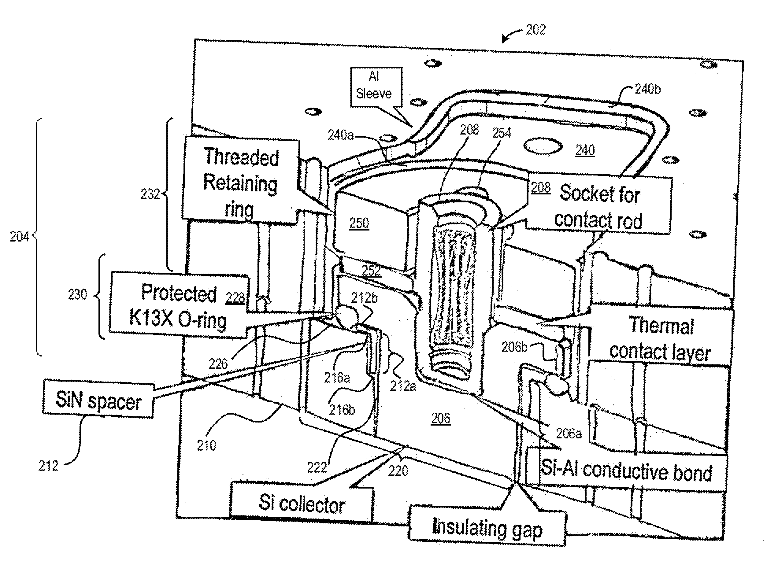
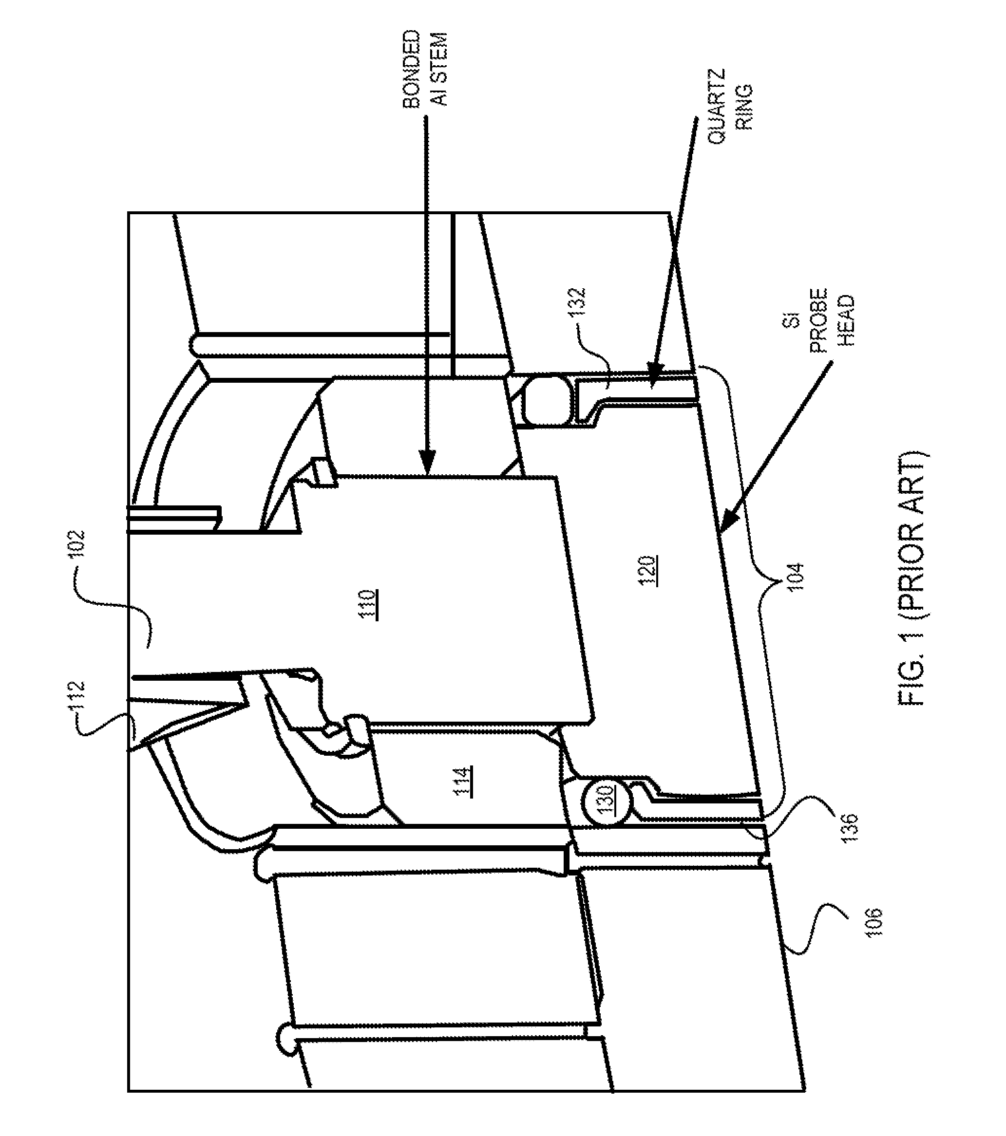
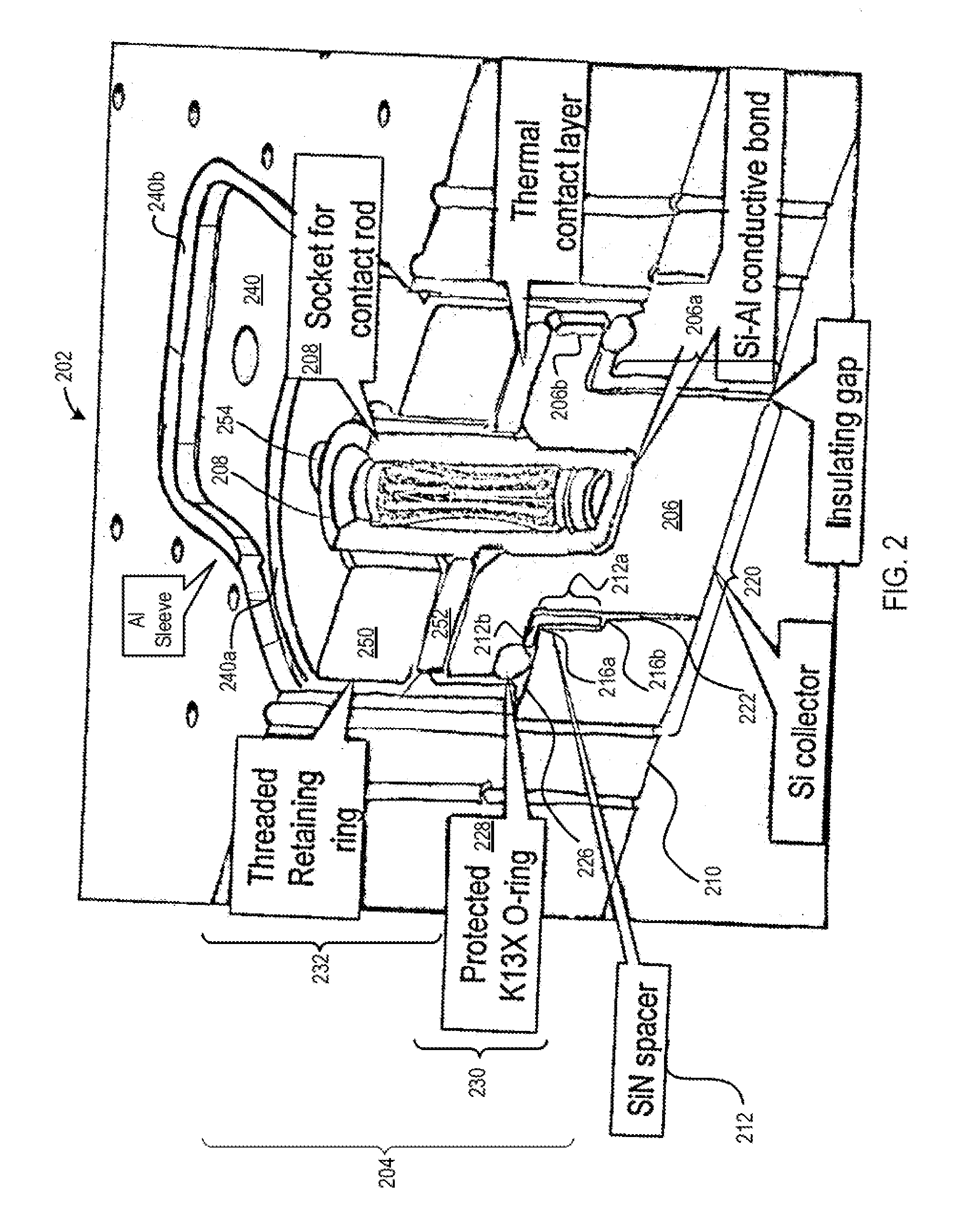
[0018]Embodiments of the invention relate to an improved ion flux design in which the direct plasma exposure of the dielectric material of the insulating / spacer ring (such as the quartz material of quartz ring 132 of FIG. 1) has been eliminated. Further, innovative design changes, such as using a high aspect ratio vacuum gap and a sharply angled plasma-to-o-ring path, have been incorporated to lengthe...


PUM

PropertyMeasurementUnit
Lengthaaaaaaaaaa
Electrical conductivityaaaaaaaaaa
Diameteraaaaaaaaaa

Abstract

An arrangement for measuring process parameters within a processing chamber is provided. The arrangement includes a probe arrangement disposed in an opening of an upper electrode. Probe arrangement includes a probe head, which includes a head portion and a flange portion. The arrangement also includes an o-ring disposed between the upper electrode and the flange portion. The arrangement further includes a spacer made of an electrically insulative material positioned between the head portion and the opening of the upper electrode to prevent the probe arrangement from touching the upper electrode. The spacer includes a disk portion configured for supporting an underside of the flange portion. The spacer also includes a hollow cylindrical portion configured to encircle the head portion. The spacer forms a right-angled path between the o-ring and an opening to the processing chamber to prevent direct line-of-sight path between the o-ring and the opening to the processing chamber.

Description

PRIORITY CLAIM[0001]This application is related to and claims priority under 35 U.S.C. §119(e) to a commonly assigned provisional patent application entitled “Plasma-facing Probe Arrangement Including Vacuum Gap For Use In A Plasma Processing Chamber,” by Booth et al., Attorney Docket Number P1831P / LMRX-P164P1, application Ser. No. 61 / 078,745, filed on Jul. 7, 2008, which is incorporated by reference herein.BACKGROUND OF THE INVENTION[0002]Plasma processing systems have long been employed to process substrates into finished electronic products for creating integrated circuits (ICs). Plasmas may be generated using a variety of plasma generation technologies, including for example inductively coupled plasma, capacitively coupled plasma, microwave, electron-cyclotron resonance (ECR), etc.[0003]During the processing of a substrate, it is highly desirable to accurately and timely monitor various process parameters inside the plasma processing chamber. Plasma-facing probe or sensor techni...

Claims


Application Information

Patent Timeline
IPC IPC(8): G01R1/06
CPCG01R19/0061H01J37/32935H01J37/32577H01J37/32541H01L21/205H01L21/3065H01L22/00
Inventor BOOTH, JEAN-PAULKEIL, DOUGLAS
Owner LAM RES CORP
Why Eureka
Try Eureka