
Method and apparatus for power-limiting electrical access

a technology of electrical access and method, applied in non-electric variable control, process and machine control, instruments, etc., can solve the problems of increasing the risk of damage to electrical and electronic equipment, community blackouts, and overload conditions of many electric power distribution systems, and achieve the effect of reducing power surges

Inactive Publication Date: 2010-01-14
KATES LAWRENCE
View PDF50 Cites 40 Cited by
  • Summary
  • Abstract
  • Description
  • Claims
  • Application Information

AI Technical Summary

Benefits of technology

[0015]Other problems are solved by a system for load control in an electrical power system where one or more load-control devices are provided to reduce system load by selectively shutting down relatively high-load equipment such as, for example, air-conditioning systems, a refrigeration systems, a pool pump systems, electric ovens, and the like. The load control devices are configured to receive commands for controlling the relatively high-load system. A power authority, such as a power utility, governmental agency, power transmission company, and / or authorized agent of any such bodies, sends one or more commands to the data interfaced devices to adjust loading on the electrical power system. The ability to remotely shut down electrical equipment allows the power authority to provide an orderly reduction of power usage. Power surges can be avoided because the remote shutdown facility can schedule a staggered restart of the controlled equipment. The power load can be reduced in an intelligent manner that minimizes the impact on businesses and personal lives. In one embodiment, power usage is reduced by first shutting down relatively less important equipment, such as, for example, pool filter pumps, hot water heaters, electric ovens, etc. If further reduction in load is required, the system can also shut down relatively more important equipment such as, for example, refrigerators, air-conditioners, and the like on a rolling basis. Relatively less important equipment (and other equipment that can be run during the night or other low-load periods) such as pool filter pumps can be shut down for extended periods of time.
[0019]In one embodiment, the system sends shutdown and startup commands. In one embodiment, the system sends shutdown commands that instruct electrical equipment to shut down for a specified period of time. In one embodiment, the shutdown time is randomized to reduce power surges when equipment restarts.

Problems solved by technology

The increasing demand for electrical energy often produces overload conditions on many electric power distribution systems, particularly during periods of extreme temperatures when consumers are calling for high levels of energy to satisfy their cooling needs.
When the customers' demand for energy reaches a given high level, communities are forced to endure rolling blackouts.
Severe power shortages increase the risk of damage to electrical and electronic equipment.
Brownouts can occur at times of extremely high power consumption or power shortages when electric utilities reduce the voltage supply to conserve energy.
Brownouts can cause computer resets, memory loss, data loss, and in some cases, overheat electronic equipment components.
Motors (e.g., fan motors and air-conditioner compressor motors compressors) can also overheat and burn out.
Blackouts are sustained power interruptions caused by overloads, storms, accidents, malfunctions of utility equipment, or other factors.
Longer-term power outages can last from hours to days.
Rolling blackouts reduce the stress on the electrical power grid, but they are very disruptive to businesses and personal lives.
Electrical and electronic equipment is often damaged after a utility brownout or blackout when the power is turned back on and a burst of electricity surges through the lines.
Equipment can fail because of a sudden lack of power, lower voltage levels, power surges when service is restored.

Method used


Image

  • Method and apparatus for power-limiting electrical access
  • Method and apparatus for power-limiting electrical access
  • Method and apparatus for power-limiting electrical access

Examples


Embodiment Construction

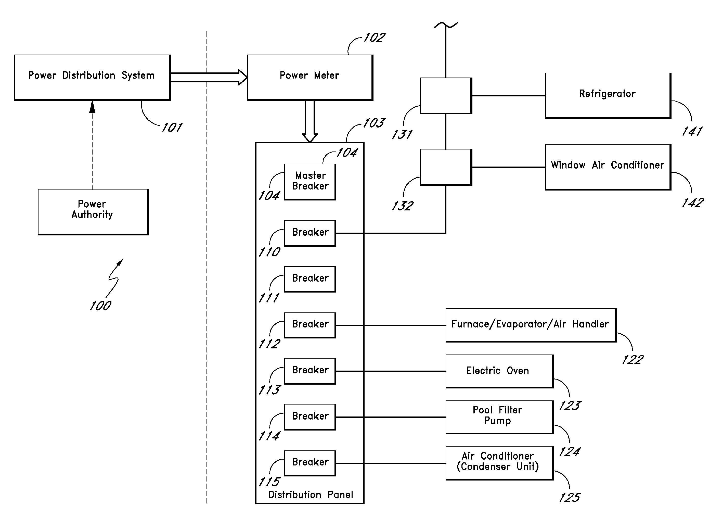
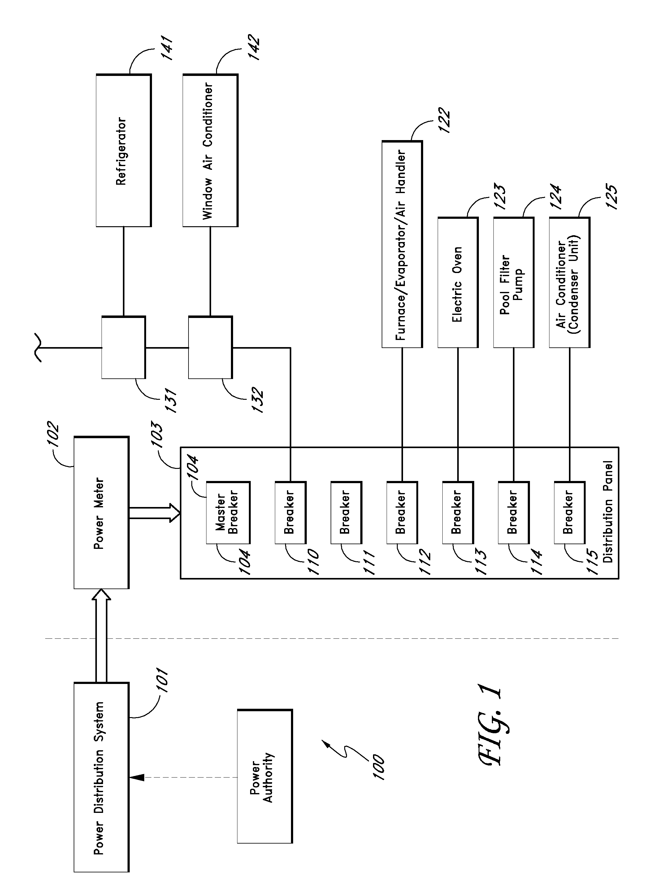
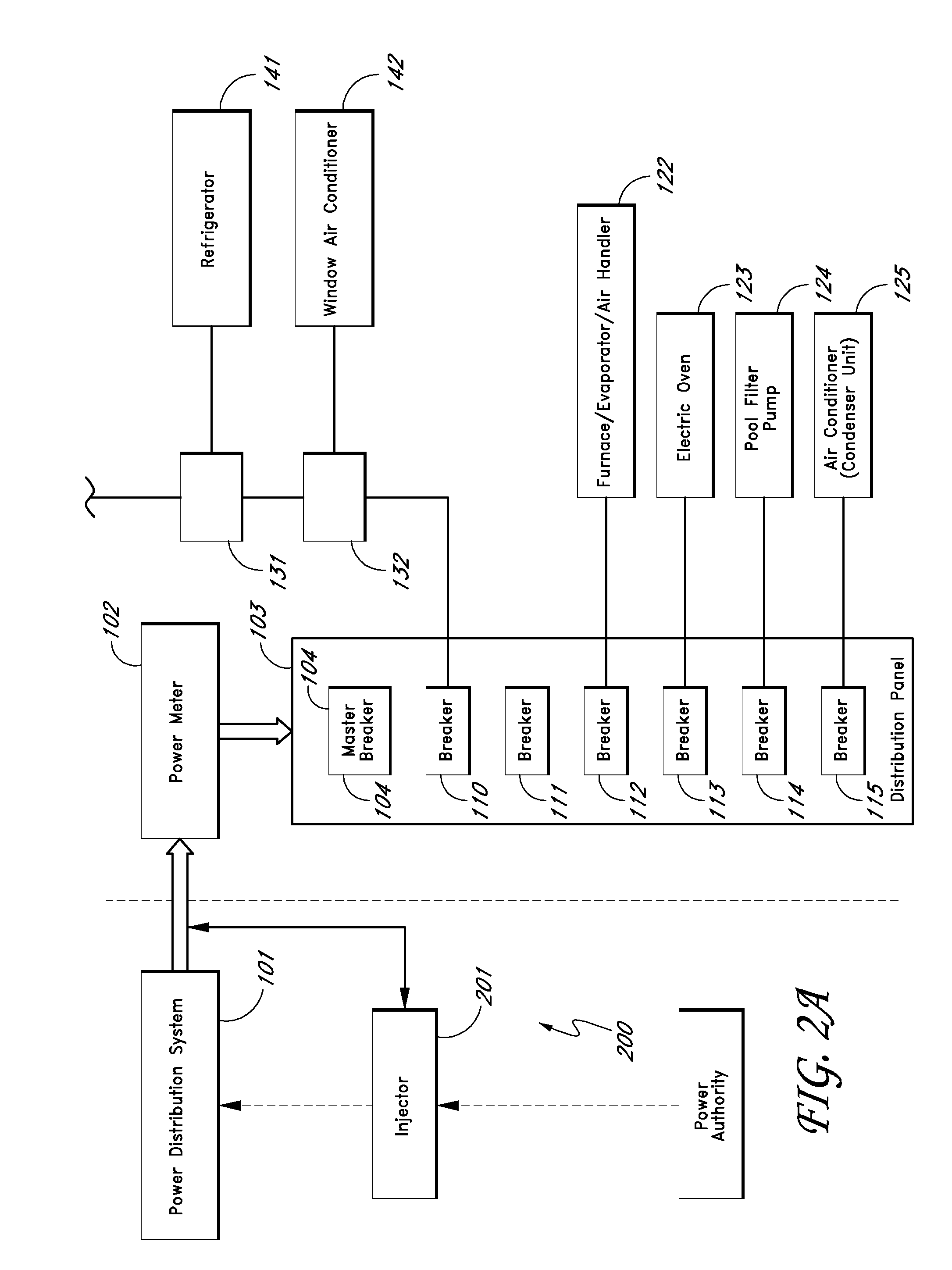
[0043]FIG. 1 shows an electrical system 100 for a home or commercial structure. In the system 100, electrical power from a distribution system 101 is provided to a power meter 102. The power meter 102 measures electrical power provided to a distribution panel 103. In the distribution panel 103, power from the meter 102 is provided to a master circuit breaker 104. Electrical power from the master circuit breaker 104 is provided to various branch circuit breakers 110-115. The branch circuit breakers 110-115 provide electric power to various branch circuits in the home or commercial structure. It is common practice to provide a dedicated branch circuit breaker to relatively high-load devices, such as, for example, electric dryers, electric ovens, electric ranges, electric water heaters, electric furnaces, building air-conditioners, pool filter pumps, etc. Thus, for example, in FIG. 1, the breaker 112 provides electrical power to a furnace / evaporator / air-handler unit, the breaker 113 pr...


PUM


Abstract

A system for load control in an electrical power system is described, wherein one or more load-limiting devices such as outlets and / or lighting sockets are provided to a home or building. The load-limiting devices conserve power and increase safety by not allowing a user to attach a device that draws excess power. Unlike circuit breakers and fuses, the load-limiting devices automatically resume normal operation when the excess load is removed. In one embodiment, the power authority sends commands to tell the load-monitoring device to provide reduced power service. In one embodiment, the commands are time-limited, thereby allowing the electric power device system to resume normal operation after a specified period of time. In one embodiment, the commands include query commands to cause the control device to report operating characteristics (e.g., efficiency, time of operation, etc.) back to the power authority.

Description

BACKGROUND[0001]1. Field of the Invention[0002]The invention relates to systems for reducing load on an electric power system to avoid brownouts and blackouts.[0003]2. Description of the Related Art[0004]The increasing demand for electrical energy often produces overload conditions on many electric power distribution systems, particularly during periods of extreme temperatures when consumers are calling for high levels of energy to satisfy their cooling needs. When the customers' demand for energy reaches a given high level, communities are forced to endure rolling blackouts.[0005]Severe power shortages increase the risk of damage to electrical and electronic equipment. Brownouts can occur at times of extremely high power consumption or power shortages when electric utilities reduce the voltage supply to conserve energy. Brownouts can cause computer resets, memory loss, data loss, and in some cases, overheat electronic equipment components. Motors (e.g., fan motors and air-condition...

Claims


Application Information

Patent Timeline
Patent Type & Authority Applications(United States)
IPC IPC(8): G06F19/00
CPCH02J3/14H02J13/0075Y02B70/3225Y04S40/126Y02B70/3266Y04S20/242Y02B90/2653Y04S20/222H02J2310/14H02J13/00017H02J13/00024H02J13/00026H02J13/00004H02J13/00034Y02B70/30Y02B90/20Y04S40/124H02J2310/60
Inventor KATES, LAWRENCE
Owner KATES LAWRENCE
Learn More