System and method for pump control

a technology of fluid pump and system, applied in the field of pumps, can solve the problems of inaccuracy of pump control, sudden or rapid change of flow demands of the fluid system, and general problems of high-pressure fluid system with spikes of high pressure, and achieve the effect of accurate prediction

Inactive Publication Date: 2010-01-21
TRANSONIC COMBUSTION
View PDF13 Cites 30 Cited by
  • Summary
  • Abstract
  • Description
  • Claims
  • Application Information

AI Technical Summary

Benefits of technology

[0010]In another embodiment, the pump system allows the rotational displacement vs. output pressure relationship to be learned or automatically tuned to the system parameters and accurately predicted by monitoring the pressure and rotational displacement values of the accumulator and the tachometer, respectively. In this way, the pressure of the pump system can be controlled independent of the speed of the engine to which the pump system is attached. The engine is preferably an internal combustion engine having one or more fuel injectors supplied with fuel from the accumulator.

Problems solved by technology

However, the relationship of flow rate (pump volume) output vs. the motor rotational displacement is normally not linear.
Thus, this assumption can lead to inaccurate pump control.
The flow demands of the fluid system may also change abruptly or rapidly over a short amount of time.
Conventional high-pressure fluid systems generally have problems with high pressure over spikes when the flow demand is decreased.
This increases wear and tear and may cause damage to components of the fluid system.

Method used


Image

  • System and method for pump control
  • System and method for pump control
  • System and method for pump control

Examples


Embodiment Construction

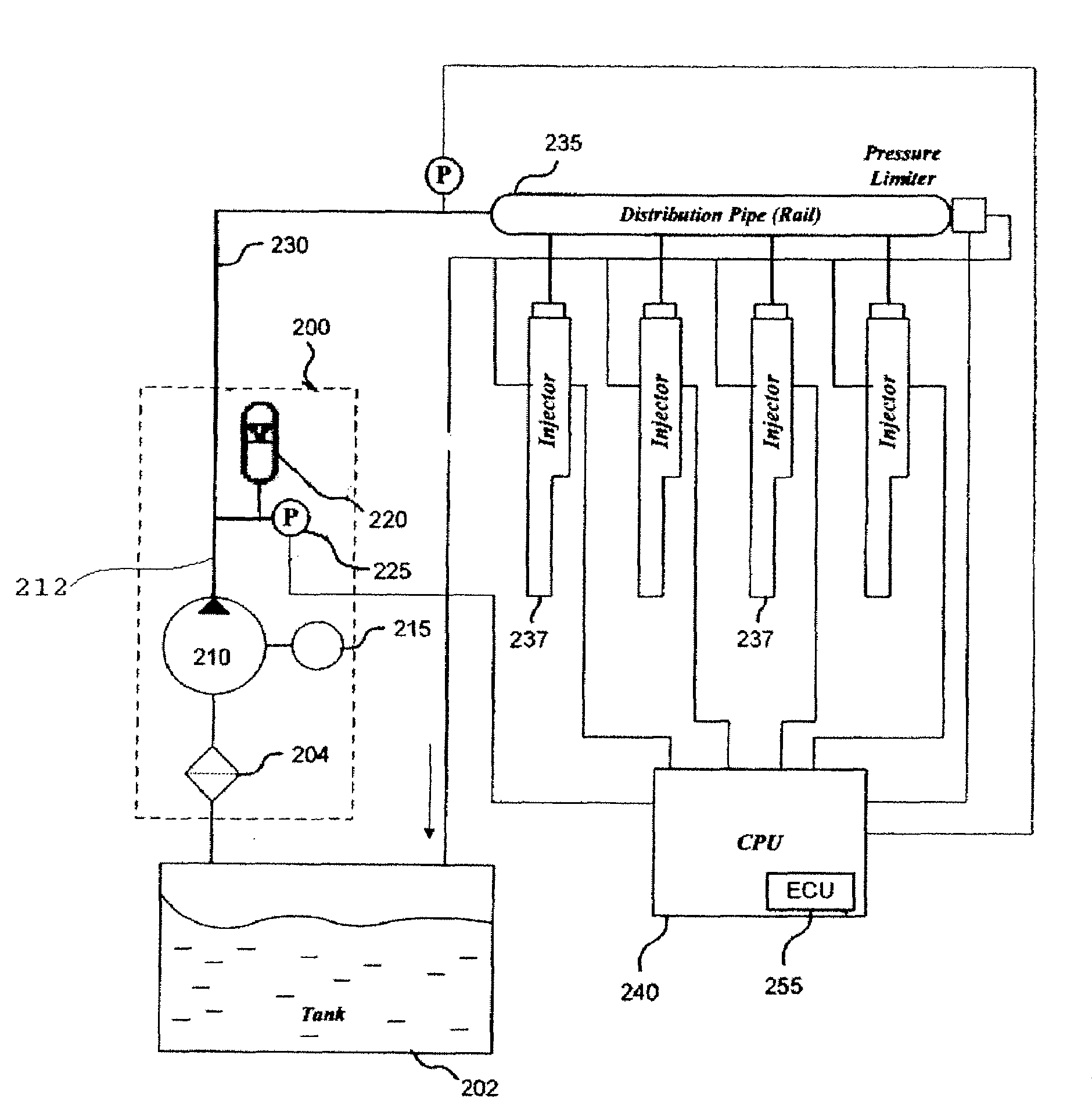
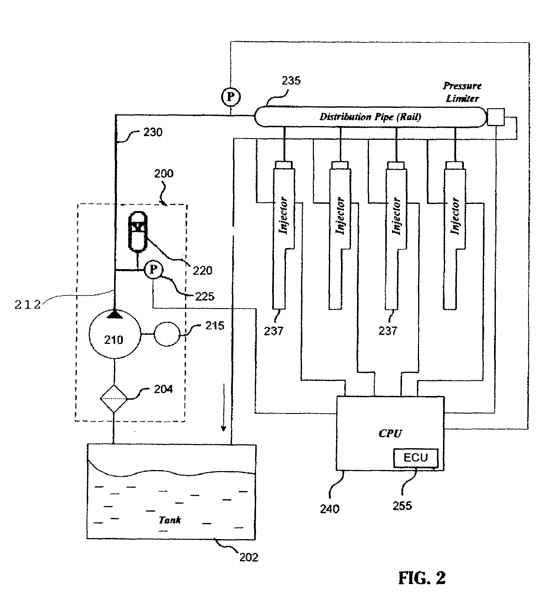
[0007]According to various embodiments of the invention, a pump system having an accurate pump control is provided. The pump system uses a positive displacement pump that may be driven by a brushless direct current motor. Other types of motor can also be employed. The fluid system includes a pump, an accumulator, a pressure sensor, and a tachometer pulse counter.

[0008]In one embodiment, the tachometer is coupled to the drive shaft of the pump motor. Particularly, the tachometer may be coupled to the motor in a way that allows the tachometer to measure and record the number of revolutions of the motor and the position of the drive shaft. The tachometer can be one or more position sensor.

[0009]The accumulator is used to control the pressure of the pump system. In one embodiment, the pressure sensor is integrated into the accumulator. The pressure sensor can be configured to measure the pressure within the accumulator and to output a signal representative of the pressure value.

[0010]In...


PUM


Abstract

The present invention is a method and system for controlling a motor attached to a variable displacement pump for providing a supercritical fuel and fuel pressure to a plurality of fuel injectors of a vehicle engine. The system includes: a pump having a motor; a tachometer sensor for measuring a rotational displacement of a motor shaft and for sending a tachometer count value to a memory device; an engine control unit configured to generate a rotational displacement vs. pressure profile of the pump based on the displacement value and pressure value; an accumulator attached to the output of the pump; and a control method that allows for a look ahead and prediction of the pump requirements needed in a future cycle based on current demand to allow for an efficient fuel injection pump.

Description

RELATED APPLICATIONS[0001]This applications claims the benefit of the priority of U.S. Provisional Patent Application No. 61 / 081,329 filed on Jul. 16, 2008.TECHNICAL FIELD[0002]The present invention relates to a pump, and more particularly, to methods and systems for controlling a fluid pump.DESCRIPTION OF THE RELATED ART[0003]Internal combustion engines typically use one or more fuel injectors to inject fuel into a combustion chamber of the engine. The timing of fuel injection can be controlled either electronically or mechanically. In a mechanical system, fuel injectors are generally driven by the crankshaft of the engine via belts, gears or chains. Typically, the fuel injectors are mechanically and synchronously coupled to the crankshaft such that the timing of fuel injection coincides with the intake strokes of the engine's piston. In an electronic system, fuel is generally injected into the engine's intake manifold by regulating an electric solenoid in each fuel injector. The t...

Claims


Application Information

Patent Timeline
Patent Type & Authority Applications(United States)
IPC IPC(8): F02D41/30
CPCF02D41/2416F02D41/2464F02D41/3082F02M37/08F02D2200/0602F02D2250/31F02M37/0041F02D2041/141
Inventor BECKER, RICKCHEIKY, MICHAEL C.
Owner TRANSONIC COMBUSTION
Why Eureka
Try Eureka