
Method for electromagnetically measuring physical parameters of a pipe

a technology of electromagnetic measurement and physical parameters, which is applied in the direction of instruments, surveying, and wellbore/well accessories, etc., can solve the problems of affecting the functionality of the casing, calipers cannot be used, and the casing may be subject to corrosion, etc., and achieves the effect of great accuracy

Active Publication Date: 2010-01-21
SCHLUMBERGER TECH CORP
View PDF6 Cites 28 Cited by
  • Summary
  • Abstract
  • Description
  • Claims
  • Application Information

AI Technical Summary

Benefits of technology

[0043]Thus, the invention allows extracting both the inner diameter and the ratio of magnetic permeability to electrical conductivity of the pipe with a great accuracy.

Problems solved by technology

Nevertheless, in harsh environment, the casing may be subject to corrosion that may affect its functionality.
The mechanical calipers cannot be used for the determination of casing thickness, cannot distinguish non-metallic deposits on the casing from the metallic casing itself, and may initiate corrosion by scratching the casing surface.
The ultrasonic tool cannot be used when the casing transports a fluid mixture comprising a certain quantity of gas relatively to liquid, and provides deteriorated reflected signals in the presence of surface roughness which typically arise in corroded casing.
The combinations of casings and tubings used in hydrocarbon wells often exhibit varying casing diameters that render the requirements of sufficiently strong and well-coupled magnetic flux difficult to maintain.
However, in practice, it has been found that this first-order correction is commonly insufficient in order to achieve satisfactory measurements accuracy.

Method used


Image

  • Method for electromagnetically measuring physical parameters of a pipe
  • Method for electromagnetically measuring physical parameters of a pipe
  • Method for electromagnetically measuring physical parameters of a pipe

Examples


Embodiment Construction

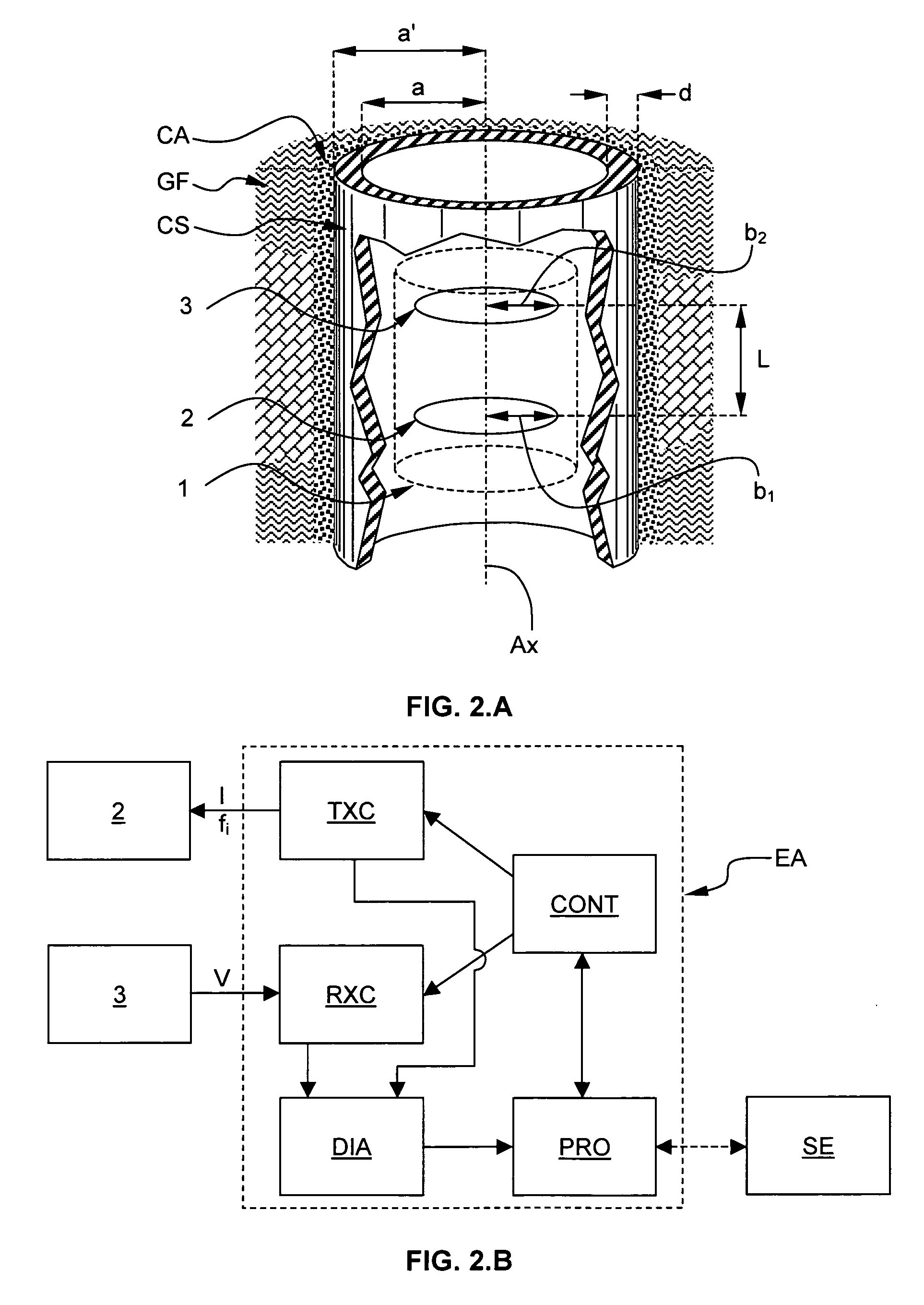
[0052]FIG. 2 shows, in a highly diagrammatic manner, the measuring arrangement 1 according to a preferred embodiment of the invention. The measuring arrangement 1 is fitted within the logging tool TL illustrated in FIG. 1. The measuring arrangement 1 comprises a first coaxial coil 2 and a second coaxial coil 3. The first coaxial coil 2 is a transmitter coil having a radius b1. The second coaxial coil 3 is a receiver coil having a radius b2.

[0053]The transmitter coil is spaced from the receiver coil by a distance L. Although, each coil is represented as an infinitesimal current loop, it will be apparent for a person skilled in the art that each coil may be a finite size coil. For example, each coil may be constructed by the superposition of individual current loops and comprises a determined number of turns. Advantageously, both coils are coaxial to the central axis Ax of the casing.

[0054]The measuring arrangement 1 is inserted within a cemented casing CS.

[0055]The casing CS is chara...


PUM


Abstract

The method electromagnetically measures a pipe inner diameter ID and a pipe ratio of magnetic permeability to electrical conductivity μ2 / σ2 by means of a measuring arrangement 1 comprising a transmitter coil 2 and a receiver coil 3, both coils being coaxial to and longitudinally spaced from each other, the measuring arrangement 1 being adapted to be positioned into the pipe CS and displaced through the pipe. The method comprises the steps of:a1) exciting the transmitter coil 2 by means of a transmitter current Ii, the transmitter current having a first excitation frequency f1,a2) measuring a receiver voltage Vi at the receiver coil 3, a3) determining a transimpedance Vi / Ii between the transmitter coil 2 and the receiver coil 3 based on the transmitter current Ii and the receiver voltage Vi, and determining a measurement ratio Mi based on said transimpedance,b) repeating the excitation step a1), the measuring step a2), the transimpedance and the measurement ratio determination step a3) for at least a second excitation frequency f2 so as to define a measurement ratio vector [M1, M2, . . . Mn],c) calculating a prediction function vector [G1, G2, . . . Gn] based on the first and at least the second excitation frequency, a plurality of potential pipe ratio of magnetic permeability to electrical conductivity and a plurality of potential pipe inner diameter ID, andd) applying a minimizing algorithm onto the measurement ratio vector [M1, M2, . . . Mn] and the prediction function vector [G1, G2, . . . Gn] and determining the pipe inner diameter and the pipe ratio of magnetic permeability to electrical conductivity corresponding to a maximum solution of the algorithm.

Description

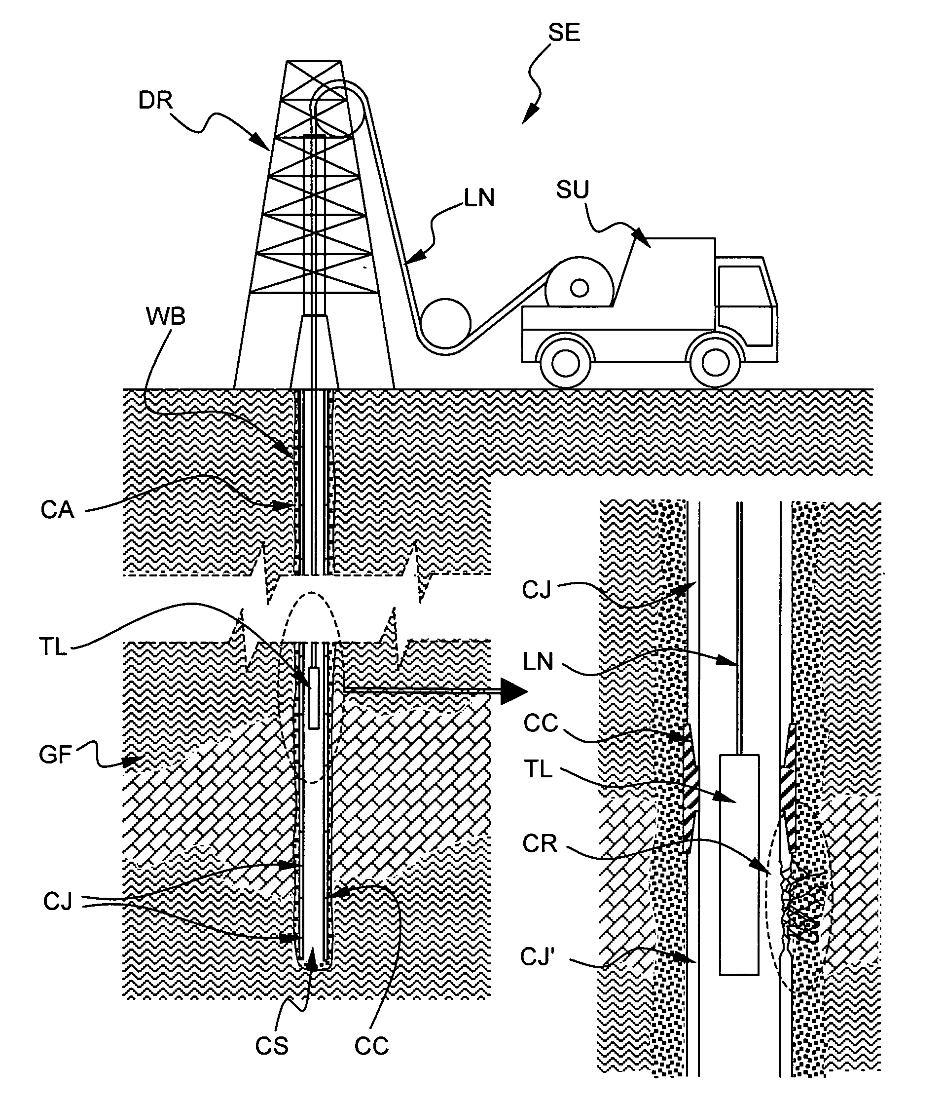
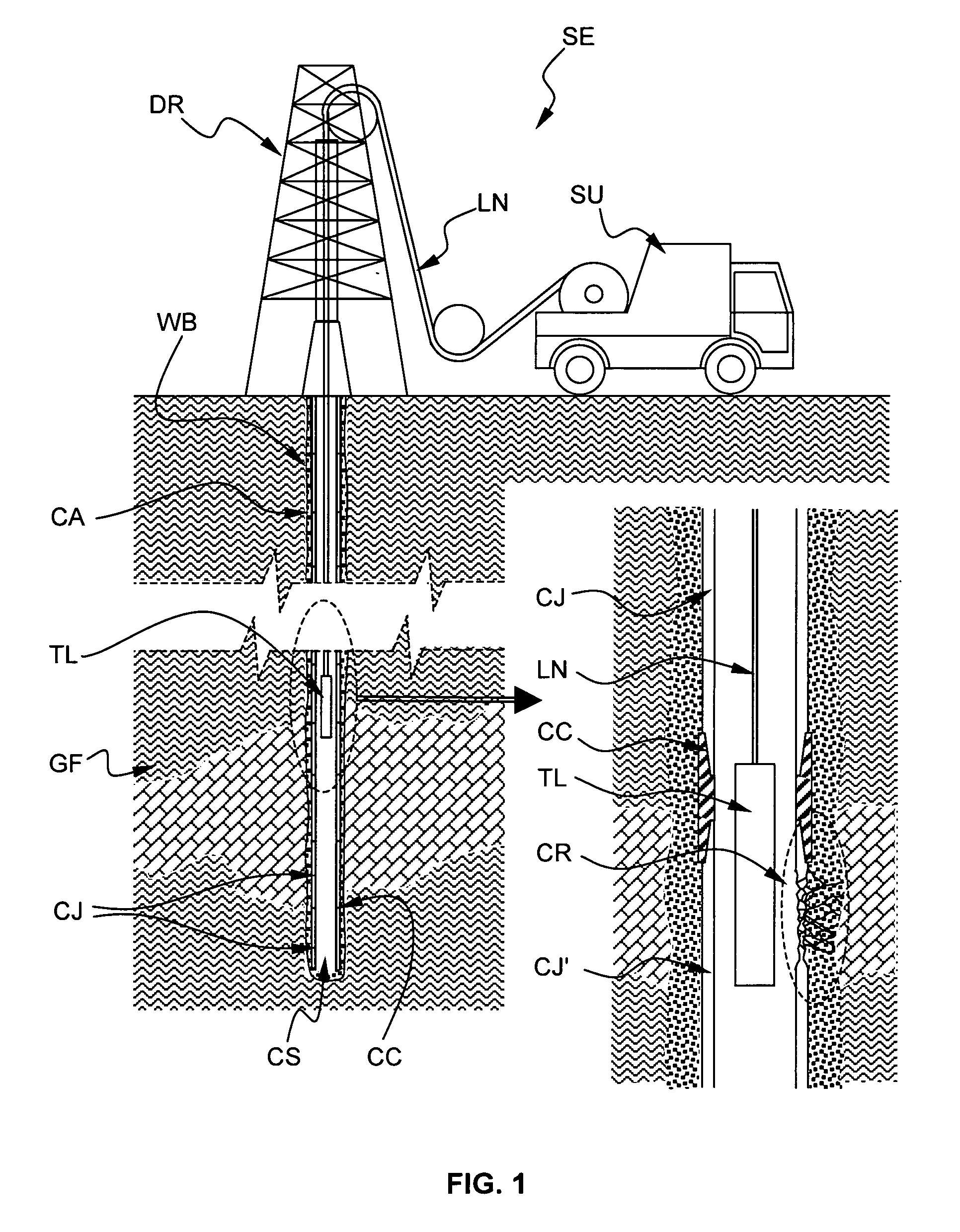
FIELD OF THE INVENTION[0001]The invention relates to a method for electromagnetically measuring physical parameters of a pipe. The physical parameters are the ratio of magnetic permeability to electrical conductivity and / or the inner diameter of the pipe.[0002]The invention is particularly well suited for implementation by a non-destructive electromagnetic inspection tool run into a ferromagnetic pipe.[0003]The invention is particularly well designed for applications in the oilfield industry.BACKGROUND OF THE INVENTION[0004]FIG. 1 schematically shows a typical onshore hydrocarbon well location and surface equipments SE above a hydrocarbon geological formation GE after a well-bore WB drilling operation has been carried out, after a casing string CS has been run and after cementing operations have been carried out for sealing the annulus CA (i.e. the space between the well-bore WB and the casing string CS).[0005]Typically, the casing string CS comprises a plurality of casing joints CJ...

Claims


Application Information

Patent Timeline
IPC IPC(8): E21B47/08
CPCE21B47/082G01N27/9046G01B7/13E21B47/085
Inventor LEGENDRE, EMMANUELBRILL, THILO M.
Owner SCHLUMBERGER TECH CORP
Learn More