Current-source gate driver

a current source gate and driver technology, applied in the field of gate drivers, can solve the problems of poor noise immunity, high switching loss, poor efficiency of vr,

Active Publication Date: 2010-01-28
GANPOWER SEMICON FOSHAN CO LTD
View PDF18 Cites 35 Cited by
  • Summary
  • Abstract
  • Description
  • Claims
  • Application Information

AI Technical Summary

Benefits of technology

[0034]In the above embodiments, the switching device may be a power switching device selected from a MOSFET (metal oxide semiconductor field effect transistor), an IGBT (insulated gate bipolar transistor), and a MCT (MOS controlled thyristor).

Problems solved by technology

However, an increase in switching frequency may lead to poor efficiency of the VR due to excessive switching loss and gate drive loss, which are proportional to the switching frequency.
More importantly, it has been shown that in applications such as a high frequency (1 MHz) synchronous buck VR, the parasitic inductance, especially the common source inductance, has a substantial propagation effect during the switching transition of the power switching devices and thus results in high switching loss [5].
[6], the power MOSFET gate was not actively clamped high or low, which resulted in poor noise immunity.
However, the leakage inductance of these approaches becomes substantial at MHz frequency.
However, all of these approaches focus on gate energy savings realized by the resonant gate driver, but do not consider the potential switching loss savings, which are more important in a VR and other switching converters operating at MHz frequencies.
However, with that approach it was not possible to achieve control of the power switching devices independently.

Method used


Image

  • Current-source gate driver
  • Current-source gate driver
  • Current-source gate driver

Examples


Embodiment Construction

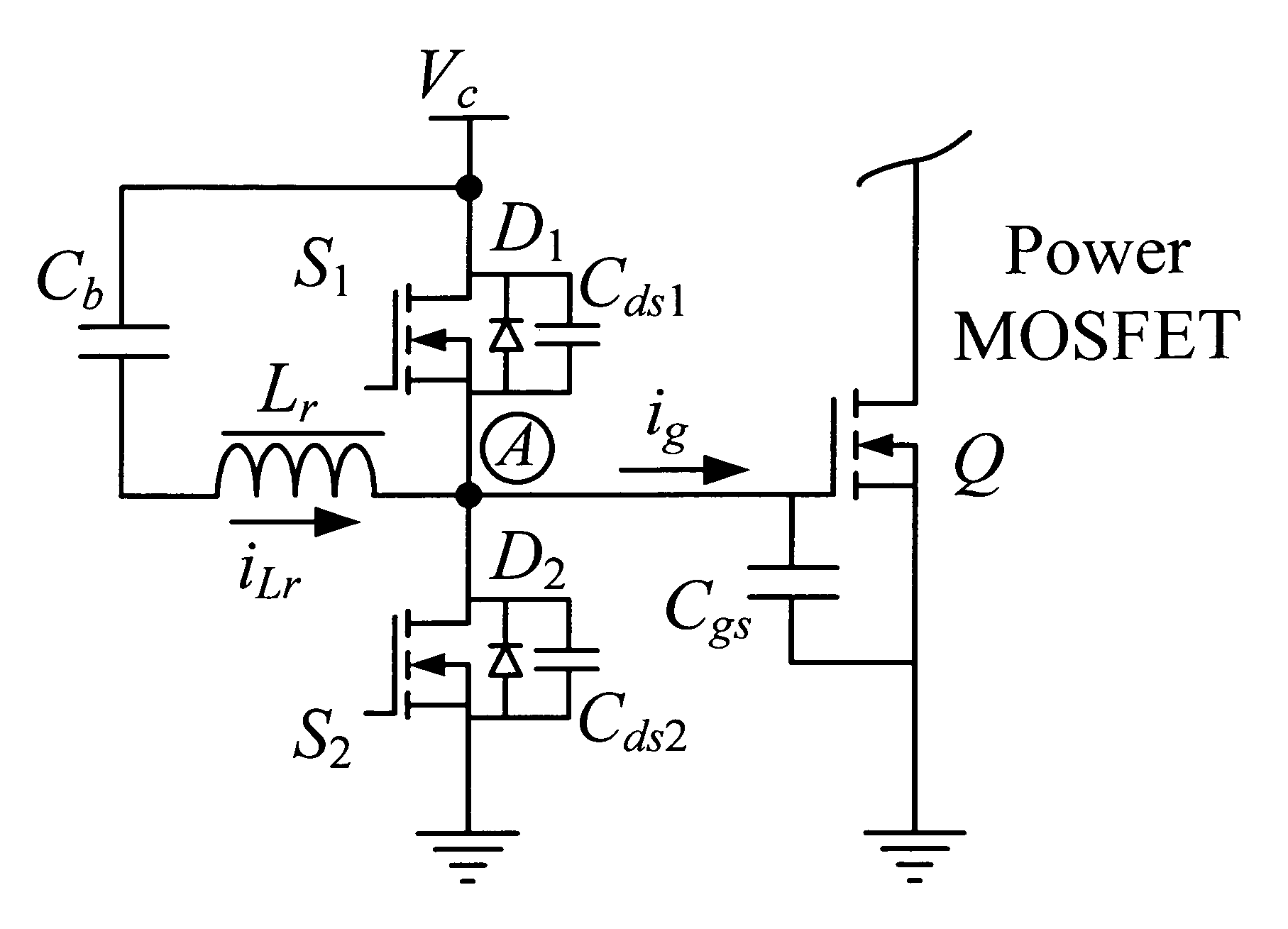
[0061]For the purpose of this description, the term MOSFET (metal oxide semiconductor field effect transistor) will be used as a non-limiting example for all switching devices, including power switching devices. It will be understood that other suitable devices, such as, for example, an IGBT (insulated gate bipolar transistor), or a MCT (MOS controlled thyristor), may be used for the power switching device. It will also be understood that other devices, such as a BJT (bipolar junction transistor, in which case a body diode (i.e., antiparallel diode) is required) may also be used for a drive switch of the current-source gate driver.

[0062]As known in the art, a switching device such as a FET has inherent capacitance. For example, for a FET, there is inherent capacitance between the gate terminal and the source terminal, between the drain terminal and source terminal, and between gate terminal and drain terminal.

[0063]As used herein, the terms “Cgs”, “gate capacitance”, “gate capacitor...


PUM


Abstract

Provided is a current-source gate driver for use with a switching device having a gate capacitance, including an input terminal for receiving a DC voltage; a first switch connected between the input terminal and an output terminal; a second switch connected between the output terminal and a circuit common; a series circuit comprising a first capacitor and an inductor, the series circuit connected between the input terminal and the output terminal; wherein the gate capacitance of the switching device is connected between the output terminal and the circuit common. The current-source gate driver improves efficiency of the power switching devices of a voltage regulator module or other switching converter.

Description

RELATED APPLICATION[0001]This application claims the benefit of the filing date of U.S. Provisional Patent Application Ser. No. 61 / 064,233, filed Feb. 22, 2008, the content of which is hereby incorporated by reference in its entirety.FIELD OF THE INVENTION[0002]This invention relates to a gate driver for use in a voltage regulator module or other switching converter. In particular, this invention relates to a current-source gate driver for improving efficiency of each of the power switching devices of a voltage regulator module independently.BACKGROUND OF THE INVENTION[0003]To meet the strict transient requirements of future microprocessors and to reduce the number of passive components required to achieve high power density, the switching frequency of voltage regulators (VR) will move into the megahertz (MHz) range in the next few years [1]-[4].[0004]However, an increase in switching frequency may lead to poor efficiency of the VR due to excessive switching loss and gate drive loss...

Claims


Application Information

Patent Timeline
Patent Type & Authority Applications(United States)
IPC IPC(8): H03K3/00
CPCH03K2217/0036H03K17/145
Inventor ZHANG, ZHILIANGLIU, YAN-FEI
Owner GANPOWER SEMICON FOSHAN CO LTD
Why Eureka
Try Eureka