
Thermal weed control

a technology of weed control and nozzle, which is applied in the direction of weed killers, flame throwers, insect catchers and killers, etc., can solve the problems of increased work effort for filling, increased transportation weight, and unpredictable task

Inactive Publication Date: 2010-02-04
ENVO DAN
View PDF4 Cites 11 Cited by
  • Summary
  • Abstract
  • Description
  • Claims
  • Application Information

AI Technical Summary

Benefits of technology

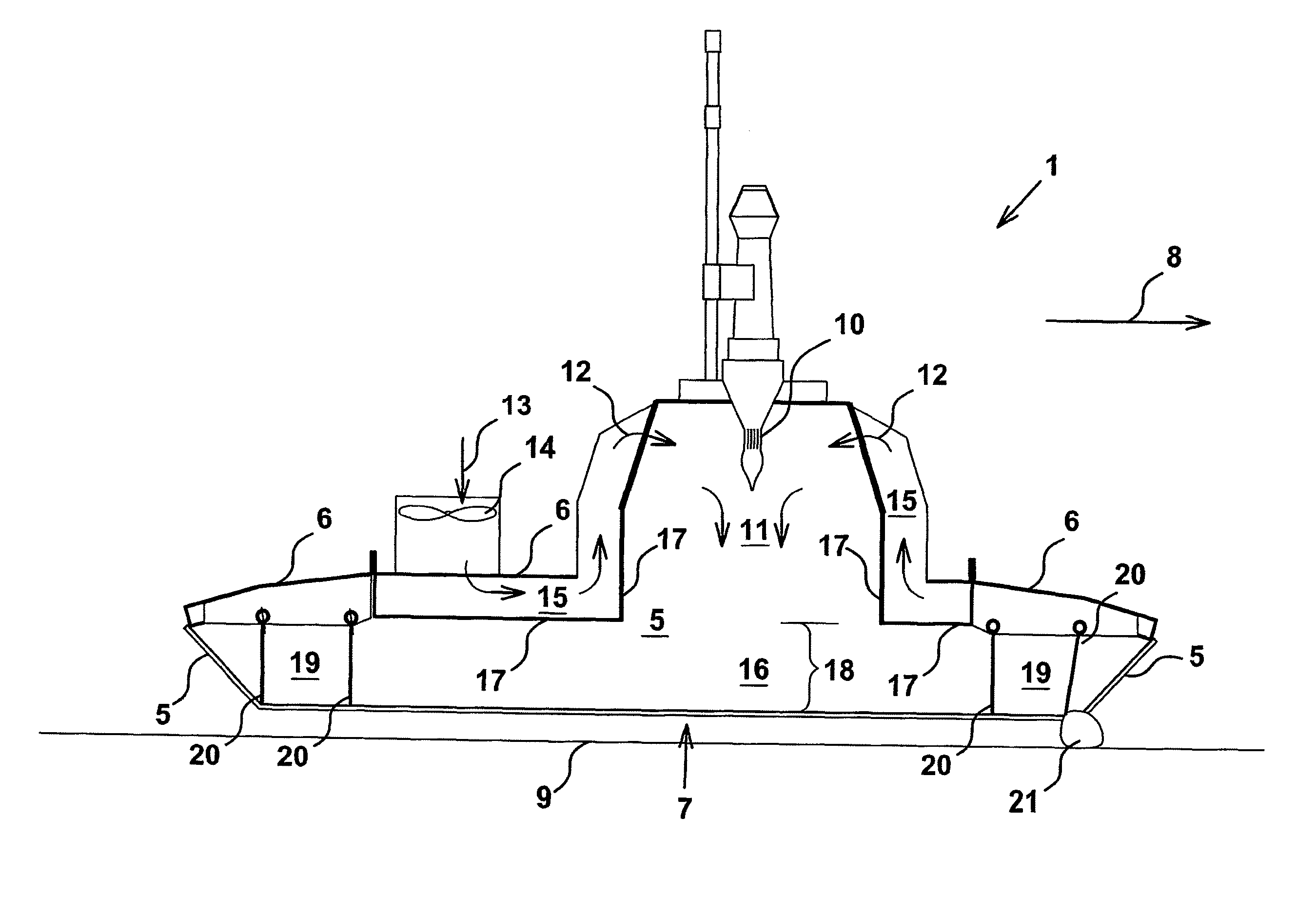
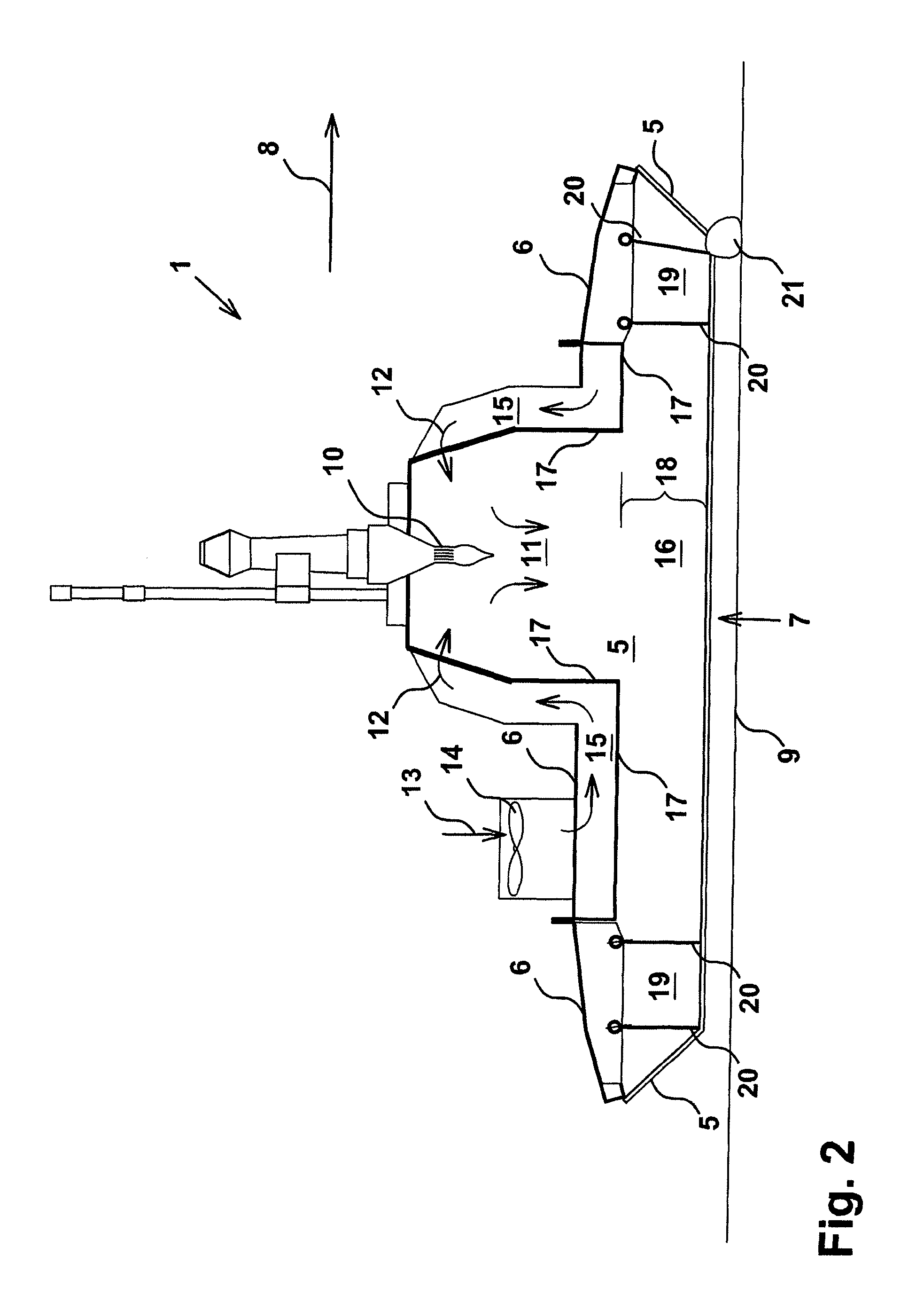
[0020]Secondly, the preheating of the secondary air, which includes combustion of gas or liquid, provides enhanced efficiency to heating means, as the amount of heat supplied via the secondary air reduces the need for combusting gas or liquid while simultaneously contributing to a more complete combustion.
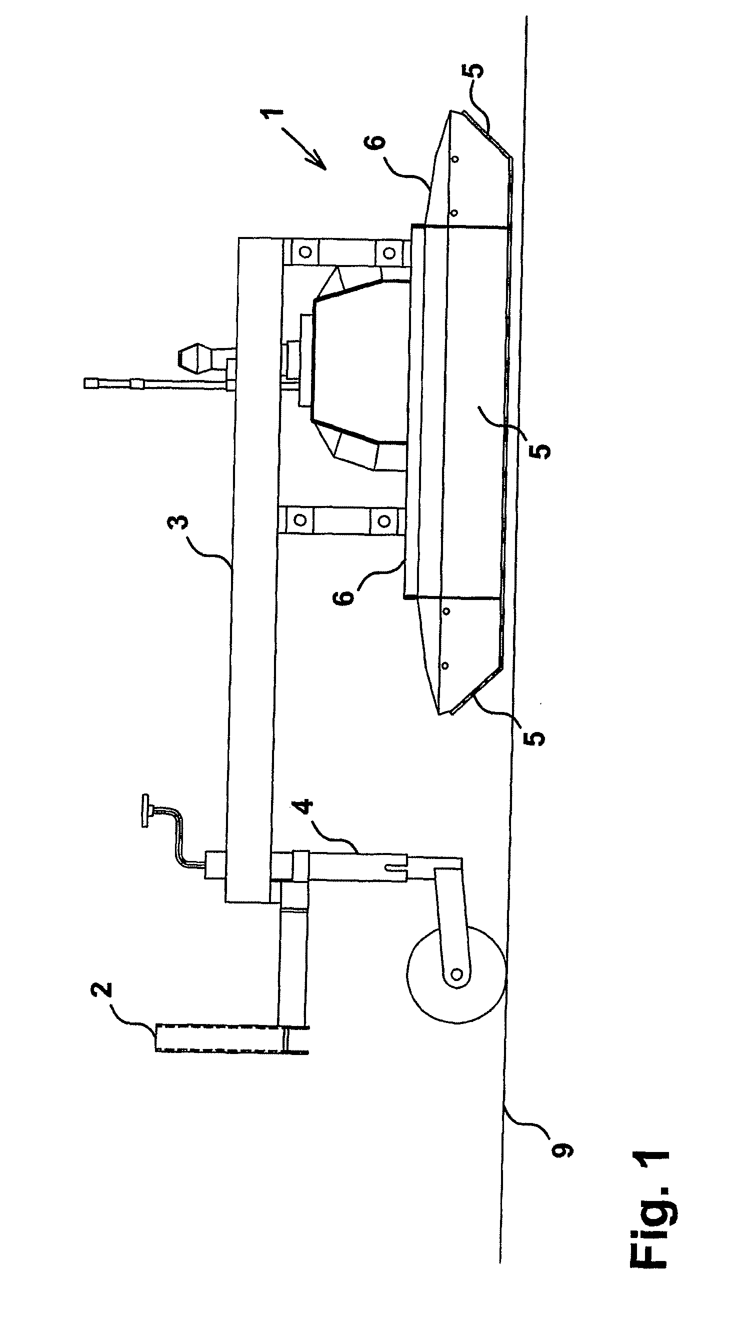
[0055]Irrespective of the technical embodiment, the weed control apparatuses described here can be designed as modules, as a modular structure enables the apparatuses to be used for weed control between plant rows and on the entire surface of the area as well. It is thus possible with a basic module having a width that fits to a preferred width of crop rows. The basic modules may be combined so as to be disposed closely when weed control is to be performed on whole surfaces, or with spacing when performing weed control between rows of crops. By weed control between rows of crops, means may be added for guiding according to the rows without damaging the crops in the rows.

Problems solved by technology

By this method, these weather conditions have meant a relatively limited time interval in which the thermal weed control could take place, thus implying a rather unpredictable and inflexible task in planning for the person performing the weed control.
Carried water or foam add extra weight for transport and added work effort for filling.
However, the external disposition of the heat supply causes a waste of heat and the risk of not attaining the desired temperature in the heat exposure area.
This, however, only implies an extra resource demanding feature in the apparatus without substantial effect as the overpressure produced thereby in the heating box causes the heat to be blown out.
The round nozzles used presently have a relatively high noise level.

Method used


Image

  • Thermal weed control
  • Thermal weed control
  • Thermal weed control

Examples


example

[0025]Combustion of propane: C3H8+5O2→3CO2+4H2O

[0026]Combustion of butane: 2C4H10+13O2→8CO2+10H2O

[0027]In order not to carry a container with a certain gas, atmospheric air is preferred as secondary air. Atmospheric air usually contains about 21% oxygen.

[0028]The apparatus may include means for feeding particles to the supplied secondary air (12) with a particle size that may be carried with the air flow in the secondary air (12), where the particles are any kind of solid or liquid, preferably combustible particles, e.g. coal dust, sawdust or atomised rape oil.

[0029]The means for this supply of secondary heating resources include a storage module which communicates with the secondary air flow, so that the particles are evenly distributed in the airflow and by this be carried to the heating area.

[0030]By supplying secondary heating resources, the need for resources from the primary heating means may thereby be reduced so that e.g. the fossil fuels propane and butane may be saved by a...


PUM


Abstract

The invention concerns a weed control apparatus and a method for thermal weed control, wherein the weed control apparatus has a heating area to which is supplied secondary air, where the secondary air is preheated before introducing it to the heating area, where preheating of the secondary air is preferably effected by conducting it through a preheating area, where the preheating area includes one or more ducts which are preferably only separated from the heat exposure area by a heat conducting material, e.g. an iron sheet. The preheating of the secondary air with heat from the heat exposure area firstly contributes to recycling of the heat that otherwise would radiate off the top side of the apparatus.Secondly, the preheating of the secondary air, which includes combustion of gas or liquid, provides enhanced efficiency to heating means, as the amount of heat supplied via the secondary air reduces the need for combusting gas or liquid while simultaneously contributing to a complete combustion.

Description

FIELD OF THE INVENTION[0001]The invention concerns a weed control apparatus and a method intended for thermal weed control, wherein the weed control apparatus is provided with heating means, e.g. via combustion of a combustible gas or liquid in an area which is substantially separated from the surroundings by a screen at the sides and upwards, where the apparatus is intended for moving in a direction across a surface.BACKGROUND OF THE INVENTION[0002]In order to avoid using chemicals for weed control, it is known to control unwanted growth by thermal action, for example by using a gas burner for heating the weed. By subjecting the weed to a suitable heat exposure for one second, the leaf cells of the plant are destroyed and the plant dehydrates and dies. Thermal weed control has the side effect that unwanted bacteria, fungus, snails and the germination ability of weed seeds are combated.[0003]Thermal weed control may i.a. be applied in connection with agricultural and horticultural c...

Claims


Application Information

Patent Timeline
Patent Type & Authority Applications(United States)
IPC IPC(8): A01M21/04
CPCA01M21/04
Inventor JENSEN, OLE BO
Owner ENVO DAN
Learn More