Recovery of carbon dioxide from flue gas

Inactive Publication Date: 2010-02-04
PRAXAIR TECH INC
View PDF57 Cites 107 Cited by
  • Summary
  • Abstract
  • Description
  • Claims
  • Application Information

AI Technical Summary

Benefits of technology

[0041](B) dryer apparatus coupled to said apparatus for compressing to receive said compressed carbon dioxide-containing stream, and capable of reducing the water content of said compressed carbon dioxide-containing stream to produce a dried

Problems solved by technology

Many processes for CO2 removal from streams such as oxyfuel combustion flue gas result in low recov

Method used


Image

  • Recovery of carbon dioxide from flue gas
  • Recovery of carbon dioxide from flue gas
  • Recovery of carbon dioxide from flue gas

Examples


Embodiment Construction

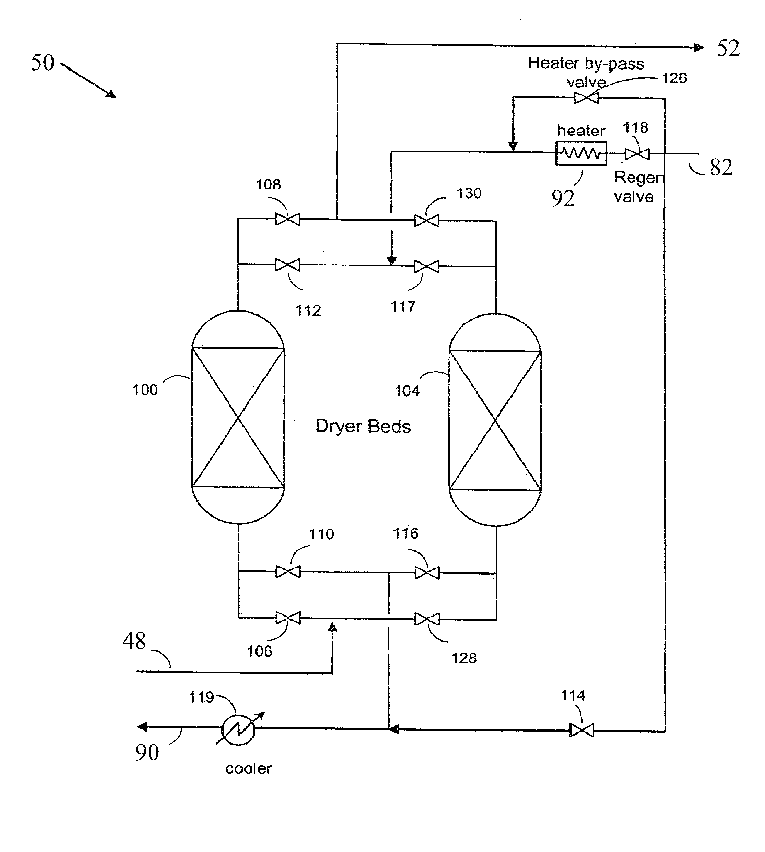
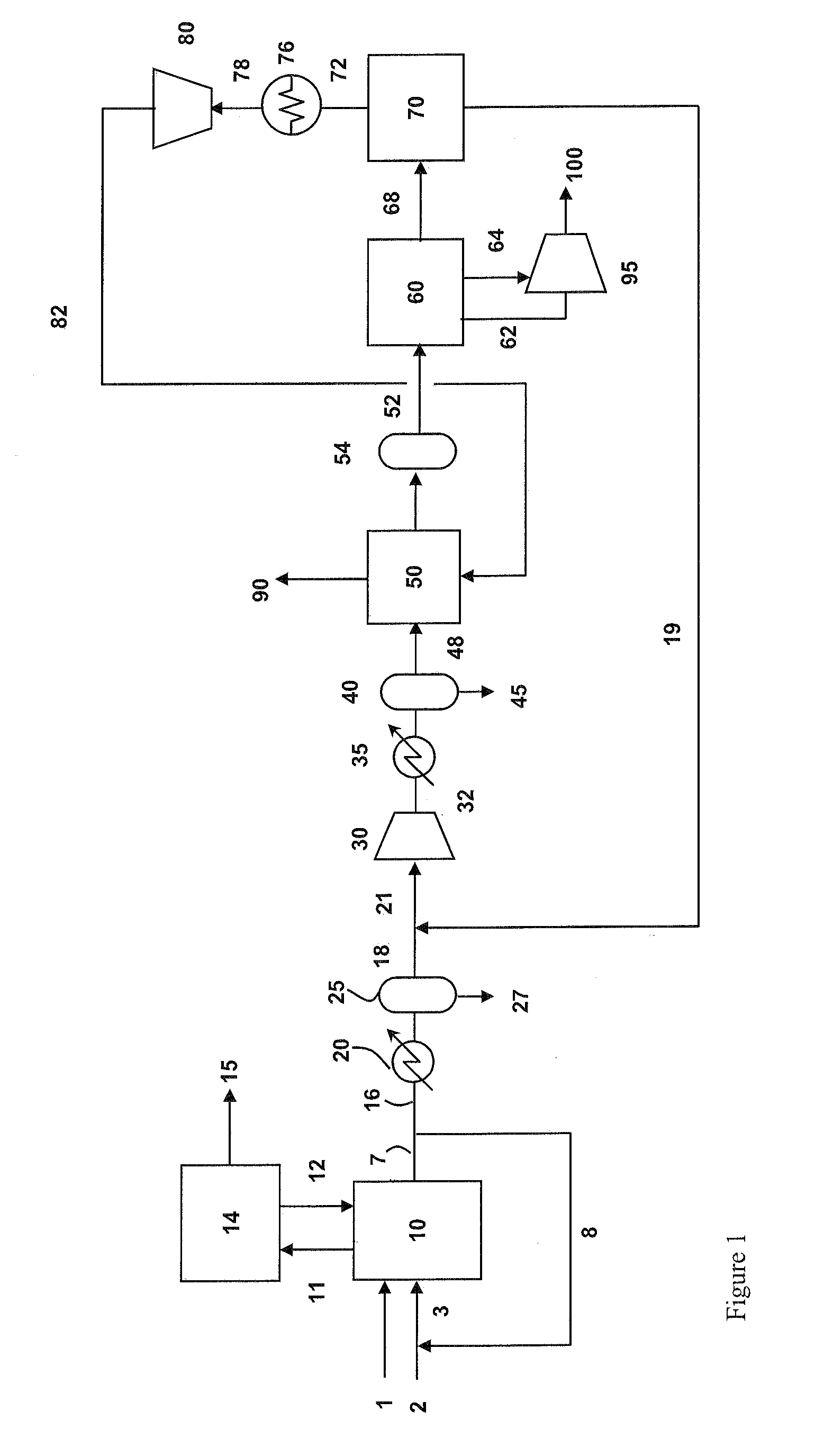
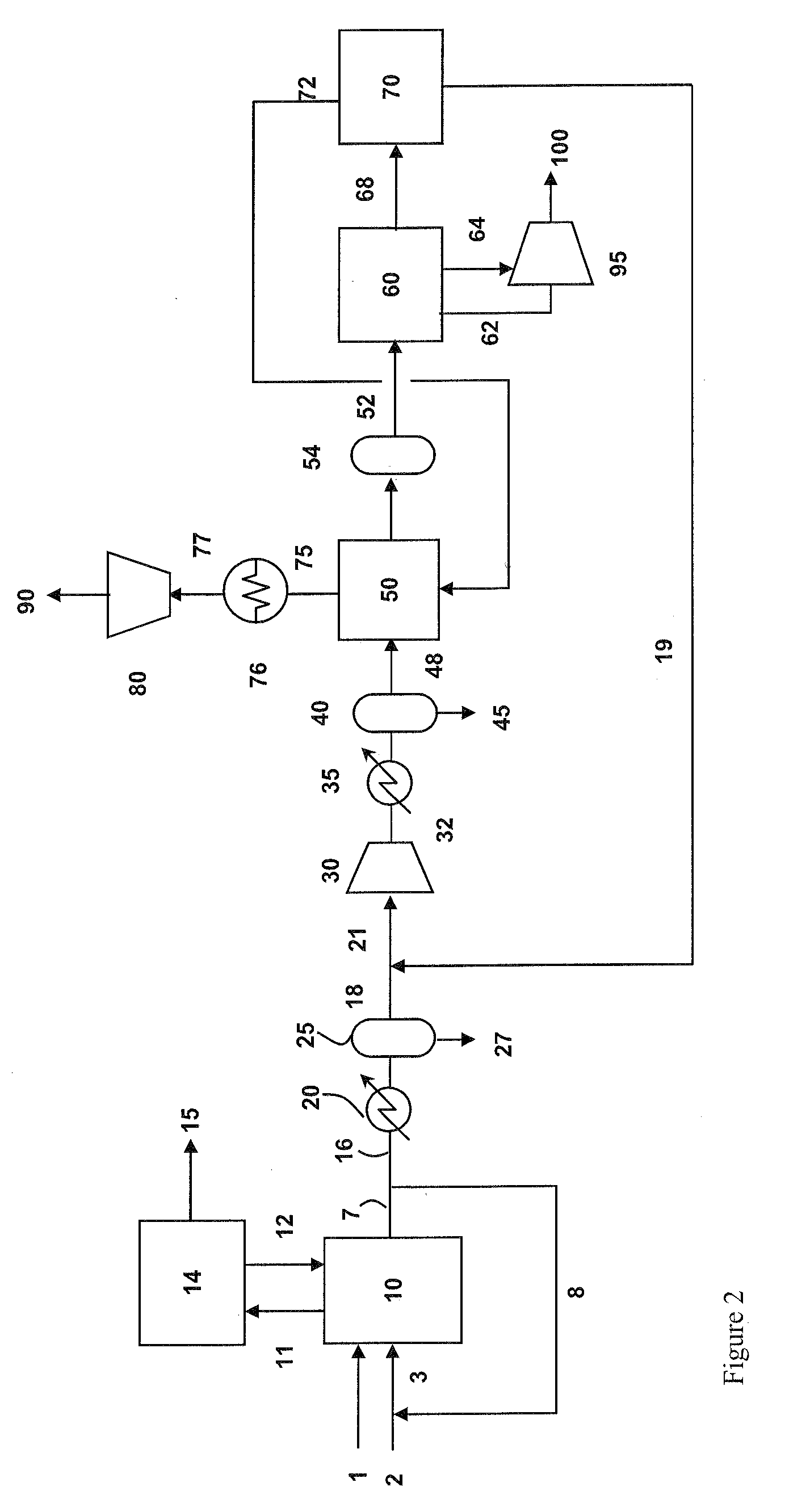
[0078]Referring to FIG. 1, oxidant stream 2 and flue gas recycle stream 8 are mixed to produce an oxidant feed stream 3. Oxidant stream 2 preferably comprises at least 80 vol. % oxygen, and preferably at least 90 vol. % oxygen.

[0079]Fuel 1 and oxidant feed stream 3 are fed to the boiler 10 and combusted in boiler 10. The preferred fuel is pulverized coal. Other fuels that may be used include combustible (preferably hydrocarbonaceous) solids, liquids and gases, such as biomass, coke, fuel oil, and natural gas, coke oven gas. The purpose of oxyfuel combustion process could be manifold: direct heating of process fluid or materials, generation of steam to be used in process or production of steam for power generation. In the embodiment shown in FIG. 1, the thermal energy released from combustion of fuel 1 with oxygen in oxidant feed stream 3 can be used in the production of steam, preferably at multiple pressures, illustrated as stream 11 of steam which is expanded in steam turbine 14 t...


PUM

PropertyMeasurementUnit
Temperatureaaaaaaaaaa
Contentaaaaaaaaaa

Abstract

Carbon dioxide-containing gas such as flue gas and a carbon dioxide-rich stream are compressed and the combined streams are then treated to desorb moisture onto adsorbent beds and then subjected to subambient-temperature processing to produce a carbon dioxide product stream and a vent stream. The vent stream is treated to produce a carbon dioxide-depleted stream which can be used to desorb moisture from the beds, and a carbon dioxide-rich stream which is combined with the carbon dioxide-containing gas.

Description

CROSS-REFERENCE TO RELATED APPLICATION [0001]The present invention claims priority to U.S. provisional patent application Ser. No. 61 / 084,423, filed Jul. 29, 2008, the entire contents of which are incorporated herein by reference in its entirety.FIELD OF THE INVENTION [0002]The present invention relates to recovering carbon dioxide from streams such as flue gas containing carbon dioxide.BACKGROUND OF THE INVENTION [0003]Many processes for CO2 removal from streams such as oxyfuel combustion flue gas result in low recovery of CO2 due to vapor liquid equilibrium limitations of CO2 mixtures, or due to other constraints. Any CO2 that is not recovered ends up in a vent stream to be released to atmosphere. Interest is growing in recovering carbon dioxide to a higher degree of recovery, in a product stream having a higher carbon dioxide content.BRIEF SUMMARY OF THE INVENTION [0004]One aspect of the present invention is a method for recovering carbon dioxide comprising[0005](A) providing a c...

Claims


Application Information

Patent Timeline
IPC IPC(8): B01D53/26B01D53/047F25J3/00C01B32/50
CPCB01D53/002Y02C10/12B01D53/261B01D53/62B01D53/75B01D53/77B01D2256/22B01D2257/404B01D2257/502B01D2257/602B01D2257/80B01D2259/40052B01D2259/40056B01D2259/402B01D2259/403B01D2259/4145F25J3/0266F25J3/067F25J2200/02F25J2200/70F25J2205/02F25J2205/04F25J2205/40F25J2205/60F25J2210/04F25J2210/70F25J2220/82F25J2230/30F25J2230/32F25J2230/80F25J2245/02F25J2270/02Y02C10/04B01D53/047F25J2205/66F25J2240/90Y02C20/40B01D53/26F25J3/00
Inventor SHAH, MINISH MAHENDRA
Owner PRAXAIR TECH INC
Why Eureka
Try Eureka