Capacitive de-ionization electrode

a deionization electrode and electrode technology, applied in the direction of fluid pressure measurement, liquid/fluent solid measurement, peptide, etc., can solve the problems of many other electrode surface materials that have yet to be tested, rapid reduction of electrical and/or mechanical properties, and time-consuming process, so as to reduce fabrication costs, reduce manufacturing costs, and facilitate the effect of electrode substrate replacemen

Active Publication Date: 2010-02-04
LAWRENCE LIVERMORE NAT SECURITY LLC
View PDF7 Cites 19 Cited by
  • Summary
  • Abstract
  • Description
  • Claims
  • Application Information

AI Technical Summary

Benefits of technology

[0011]It is an object of the present invention to provide new electrode designs that use less expensive materials, have reduced fabrication costs, allow for easy replacement of electrode substrate material and have configurations that are intrinsically safer than provided in the prior art.
[0013]The new electrode support structure for CDI incorporates standard circuit board technology which has been tailored to create an electrode that resists corrosion, is commercially (and inexpensively) fabricated, is easily assembled, reduces the risk of short circuiting, and allows for replacement of electrode substrate material. Typical circuit boards (and the prototype electrode supporting structure referenced in this application) are fabricated with fiberglass-reinforced resin with a metal clad conductive surface. The conductive surface is linked to a tab on the edge of the electrode used for connecting to the power source.

Problems solved by technology

In an effort to maximize electrode surface area, several materials (e.g., carbon aerogel) have been used as electrode surface accompaniments; however, many other electrode surface materials have yet to be tested.
Electrode material in the presence of an electrical field and a conductive solution will tend to oxidize at the cathode and reduce at the anode causing rapid reduction of electrical and / or mechanical properties and introduction of the electrode material (e.g., Cu, Fe) into solution.
This process is time consuming and may affect the performance of the carbon aerogel due to the seepage of epoxy within the aerogel matrix.
Also, titanium is expensive and, without being isolated, posed an increased risk of short-circuiting between electrodes and a shock hazard.
Titanium is expensive.
The electrodes required extensive machining.
Adhering the substrate material to the titanium surface was time consuming, and may have resulted in a reduction in surface area due to infiltration of the epoxy within the substrate matrix.
There was a high risk of short-circuiting between electrodes and a shock hazard if any metal object touched the CDI reactor.

Method used


Image

  • Capacitive de-ionization electrode
  • Capacitive de-ionization electrode
  • Capacitive de-ionization electrode

Examples


Embodiment Construction

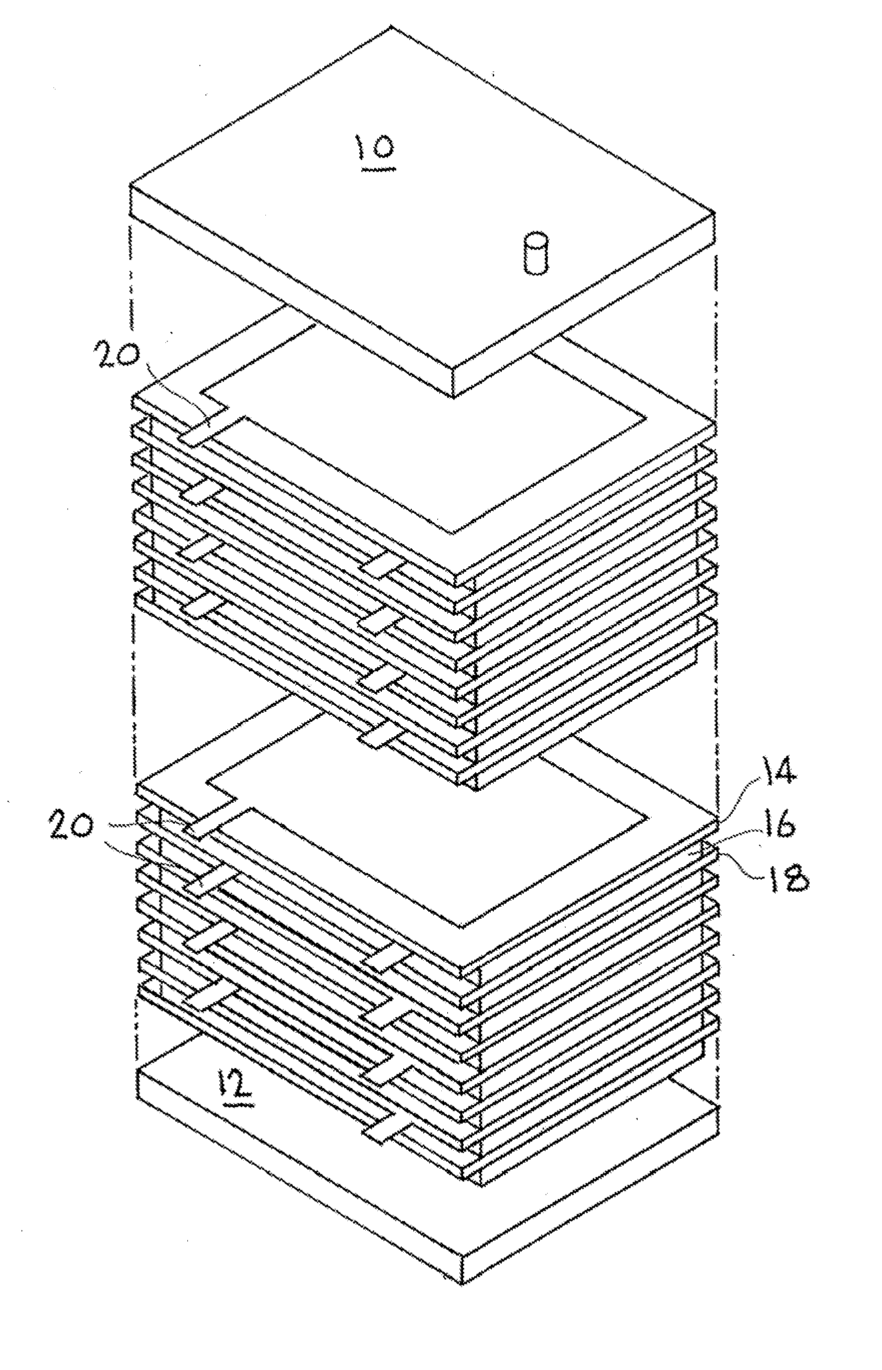
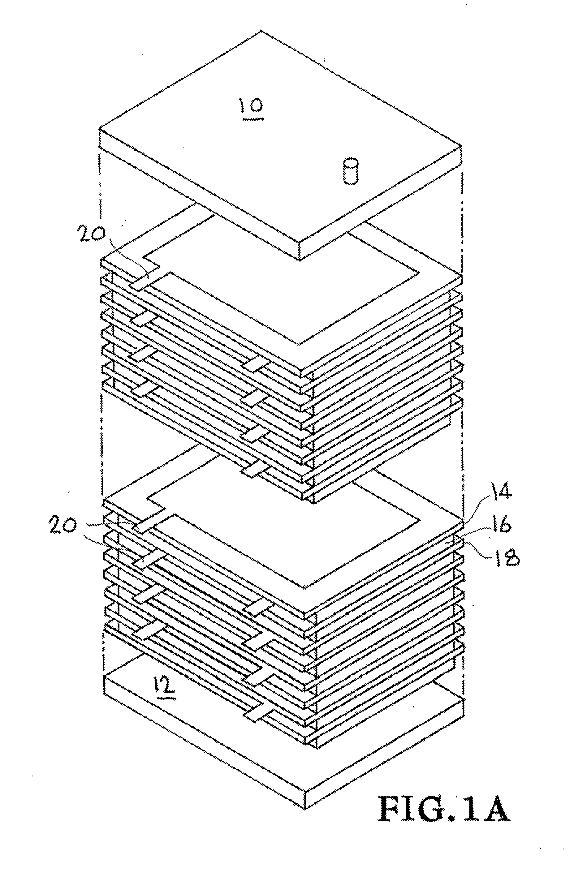
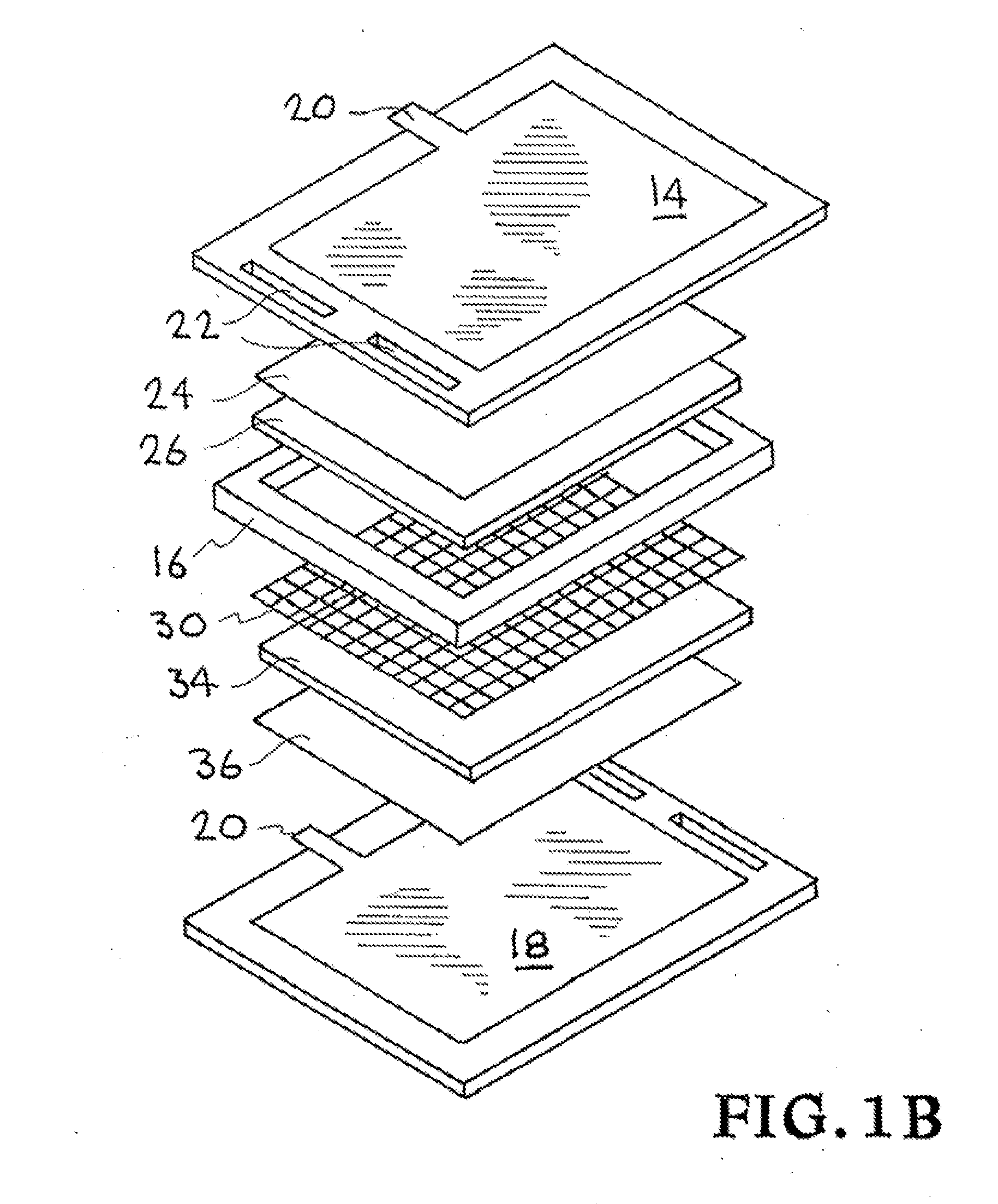
[0021]The invention provides new electrode fabrication and reactor configurations that reduce capitol costs, increase efficiency, and enable the replacement of electrode surface accompaniments. The new electrode support structures incorporate standard circuit board technology which has been tailored to create an electrode that resists corrosion, is fabricated commercially (and inexpensively), is easily assembled, reduces the risk of short circuiting, and allows for easy replacement of electrode substrate material. The electrode supporting structure can be made, e.g., of fiberglass-reinforced resin with a metal clad conductive surface. This is typically referred to as “FR4” PCB board in the circuit board industry. The conductive surface extends to the edge of the board in one or more locations to facilitate the connection of electrical power. The configuration of the new electrode “cell” consists of the fiberglass electrode support structure with the metal cladding (typically copper,...


PUM

PropertyMeasurementUnit
thickaaaaaaaaaa
thickaaaaaaaaaa
surface areaaaaaaaaaaa

Abstract

An electrode “cell” for use in a capacitive deionization (CDI) reactor consists of the electrode support structure, a non-reactive conductive material, the electrode accompaniment or substrate and a flow through screen / separator. These “layers” are repeated and the electrodes are sealed together with gaskets between two end plates to create stacked sets of alternating anode and cathode electrodes in the CDI reactor.

Description

[0001]The United States Government has rights in this invention pursuant to Contract No. DE-AC52-07NA27344 between the United States Department of Energy and Lawrence Livermore National Security, LLC.BACKGROUND OF THE INVENTION[0002]1. Field of the Invention[0003]The present invention relates to capacitive deionization technology, and more specifically, it relates to capacitive deionization (CDI) electrode fabrication and CDI reactor configurations that reduce capitol costs, increase efficiency, and enable the replacement of electrode surface accompaniments.[0004]2. Description of Related Art[0005]Capacitive deionization is a technology developed to remove ions in solution by bringing the solution between two electrodes of opposite charge. The positive ions are attracted and migrate to the negative electrode material, and the negative ions behave similarly with the positive electrode. Several different approaches to this technique have been proposed (and patented by J. Farmer, M. An...

Claims


Application Information

Patent Timeline
Patent Type & Authority Applications(United States)
IPC IPC(8): B01D57/00
CPCC02F1/46109C02F2001/46161C02F2001/46133C02F1/4691
Inventor DAILY, III, WILLIAM D.
Owner LAWRENCE LIVERMORE NAT SECURITY LLC
Why Eureka
Try Eureka