
Liquid Crystal Display

a liquid crystal display and display technology, applied in the field of liquid crystal display, can solve the problems of insufficient adhesive strength, easy cracking or breakage of semiconductor chips, etc., and achieve the effect of reducing the thickness of the liquid crystal display and efficient discharge of charges

Inactive Publication Date: 2010-02-04
JAPAN DISPLAY INC +1
View PDF12 Cites 43 Cited by
  • Summary
  • Abstract
  • Description
  • Claims
  • Application Information

AI Technical Summary

Benefits of technology

The present invention provides a liquid crystal display that can reliably adhere an elastic layer to a rigid layer, prevent the touch panel from coming into contact with the rigid layer, prevent the semiconductor chip from cracking or breaking, and efficiently discharge charges on an IPS-type liquid crystal panel. The invention includes an elastic layer, a rigid layer, and an adhesive sheet for adhering the elastic layer to the rigid layer. The elastic layer can be formed of an elastic front window or an elastic touch panel, and the rigid layer can be formed of a rigid liquid crystal panel or a rigid touch panel. The invention also includes an elastic front window and an adhesive sheet for adhering the elastic front window to the rigid layer. The technical effects of the invention include improved adhesive strength, prevention of warp and cracking of the elastic layer, prevention of contact between the touch panel and the semiconductor chip, efficient discharge of charges on the IPS-type liquid crystal panel, and the like.

Problems solved by technology

However, the ultraviolet-curing adhesive materials 11, 12 do not have a sufficient adhesive strength for adhering an elastic layer to the rigid layer before the radiation of ultraviolet rays while straightening the elastic layer having a warp.
(2) The semiconductor chip 4 is liable to be easily cracked or broken due to an impact generated when a mobile phone falls or the like.

Method used


Image

  • Liquid Crystal Display
  • Liquid Crystal Display
  • Liquid Crystal Display

Examples


embodiment 1

[0053]FIG. 1A to FIG. 1D are four schematic cross-sectional views showing representative examples of a mobile-phone-use liquid crystal display module according to an embodiment 1 of the present invention.

[0054]The mobile-phone-use liquid crystal display module shown in FIG. 1A is formed of a liquid crystal display which is constituted by stacking a liquid crystal panel (rigid layer) 20 which is formed of two glass substrates with a liquid crystal layer sandwiched therebetween, an electrostatic-capacitance-type touch panel (rigid layer) 7 which is formed of a glass substrate, for example, and a front window (elastic layer) 23 made of an acrylic resin, for example, in this order.

[0055]Here, in the same manner as a technique adopted by the related art, the rigid touch panel 7 is adhered to the rigid liquid crystal panel 20 by way of an ultraviolet-curing adhesive material 11. Further, the elastic front window 23 is adhered to the rigid touch panel 7 by way of an adhesive sheet 30 forme...

embodiment 2

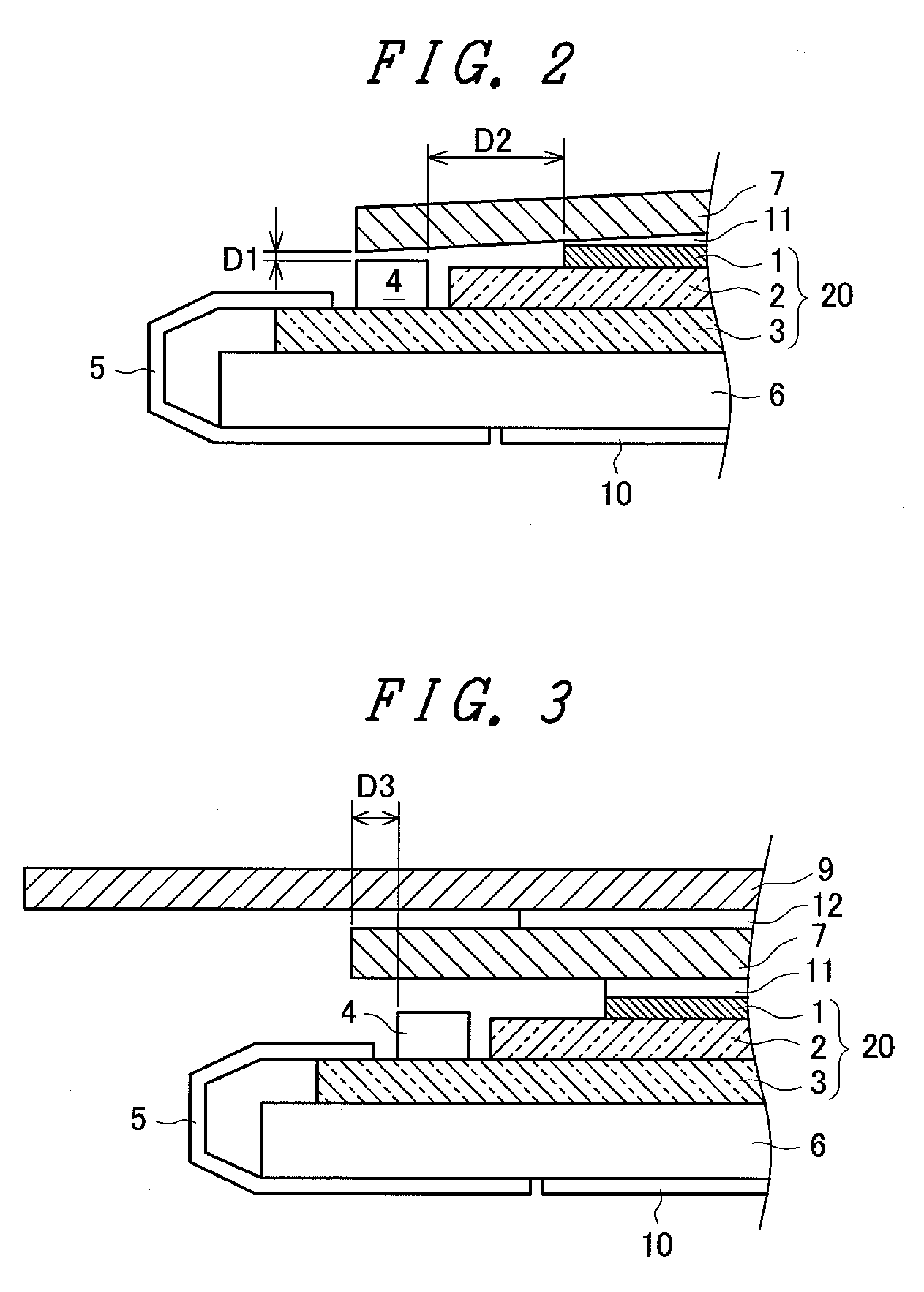
[0066]FIG. 2 is a partially cross-sectional view of a mobile-phone-use liquid crystal display module according to an embodiment 2 of the present invention.

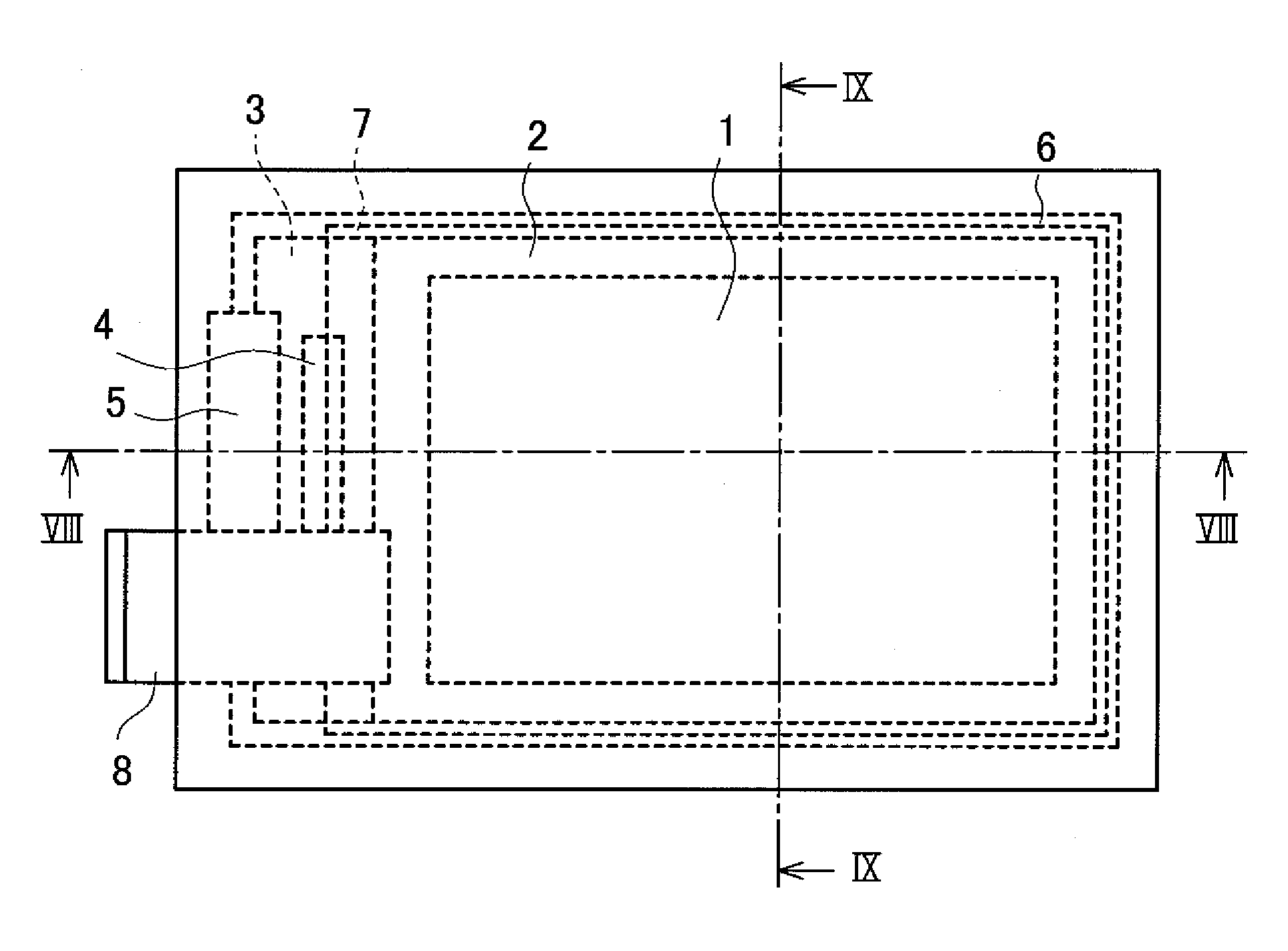
[0067]As shown in FIG. 2, the mobile-phone-use liquid crystal display module according to the embodiment 2 is formed of a liquid crystal display having the “three-layered hybrid structure”. The liquid crystal display includes a liquid crystal panel 20 which is constituted of glass substrates 2, 3 with a liquid crystal layer not shown in the drawing sandwiched therebetween and a polarizer 1 (thickness being set to approximately 0.1 mm to 0.14 mm) arranged on the glass substrate 2, a semiconductor chip 4 which is mounted on the glass substrate 3, a liquid-crystal-panel-use FPC 5 which is electrically connected to the semiconductor chip 4, a resin mold 6 which supports the liquid crystal panel 20, a reflection sheet 10, a touch panel 7 which is adhered to the polarizer 1 by way of an adhesive layer (ultraviolet-curing adhesive materi...

embodiment 3

[0076]FIG. 3 is a partially cross-sectional view of a mobile-phone-use liquid crystal display module according to an embodiment 3 of the present invention.

[0077]As shown in FIG. 3, the mobile-phone-use liquid crystal display module according to the embodiment 3 is formed of a liquid crystal display having the “three-layered hybrid structure”. The liquid crystal display includes a liquid crystal panel 20 which is constituted of glass substrates 2, 3 with a liquid crystal layer not shown in the drawing sandwiched therebetween and a polarizer 1 arranged on the glass substrate 2, a semiconductor chip 4 which is mounted on the glass substrate 3, a liquid-crystal-panel-use FPC 5 which is electrically connected to the semiconductor chip 4, a resin mold 6 which supports the liquid crystal panel 20, a reflection sheet 10, a touch panel 7 which is adhered to the polarizer 1 by way of an adhesive layer (ultraviolet-curing adhesive material) 11 and is larger than the polarizer 1 in size, a touc...


PUM

PropertyMeasurementUnit
thicknessaaaaaaaaaa
thicknessaaaaaaaaaa
thicknessaaaaaaaaaa

Abstract

A liquid crystal display which can reliably adhere an elastic layer which is liable to warp easily to a rigid layer is provided. (a) An elastic front window is adhered to a rigid touch panel by way of an adhesive sheet. (b) An elastic touch panel is adhered to a rigid liquid crystal panel by way of an adhesive sheet, and an elastic front window is adhered to the elastic touch panel byway of an adhesive sheet. (c) An elastic touch panel is adhered to a rigid liquid crystal panel by way of an adhesive sheet and, thereafter, a rigid front window is adhered to the elastic touch panel by way of an ultraviolet-curing adhesive material. (d) An elastic touch panel is adhered to a rigid front window by way of an adhesive sheet and, thereafter, a rigid liquid crystal panel is adhered to the elastic touch panel by way of an ultraviolet-curing adhesive material.

Description

CROSS-REFERENCE TO RELATED APPLICATION[0001]The disclosure of Japanese Patent Application No. 2008-197213 filed on Jul. 31, 2008 including the specification, drawings, and abstract is incorporated herein by reference in its entirety.BACKGROUND OF THE INVENTION[0002]1. Field of the Invention[0003]The present invention relates to a liquid crystal display.[0004]2. Related Art[0005]With respect to portable devices such as a mobile phone, a portable gaming machine, a digital camera and a PDA (Personal Digital Assistant), there has been known a portable device which adopts a liquid crystal display formed by stacking a liquid crystal panel, a touch panel and a front window. Such a liquid crystal display has the structure in which the liquid crystal panel and the touch panel are adhered to each other using an adhesive material, and the touch panel and the front window are adhered to each other using an adhesive material (hereinafter referred to as three-layered hybrid structure) Here, the c...

Claims


Application Information

Patent Timeline
Patent Type & Authority Applications(United States)
IPC IPC(8): G06F3/045G02F1/1335
CPCG02F1/13338G02F1/13452Y10T156/10G06F3/0412G06F3/044G02F2001/13332G06F3/0443G02F1/13332G02F1/133531G02F1/133528G02F1/1339G02F1/13439G02F1/1345G02F1/134363G02F2202/28G06F2203/04103
Inventor OOHIRA, EIJI
Owner JAPAN DISPLAY INC
Learn More