Multilayer Film-Coated Member And Method For Producing It

a film coating and multi-layer technology, applied in the direction of superimposed coating process, ion implantation coating, magnetic recording, etc., can solve the problems of limited improvement effect, difficult application of film to tools and slide members, and inability to improve so as to prevent the abraded member from being absorbed, the effect of improving the heat resistance of coating films

Active Publication Date: 2010-02-04
SULZER METAPLAS
View PDF0 Cites 11 Cited by
  • Summary
  • Abstract
  • Description
  • Claims
  • Application Information

AI Technical Summary

Benefits of technology

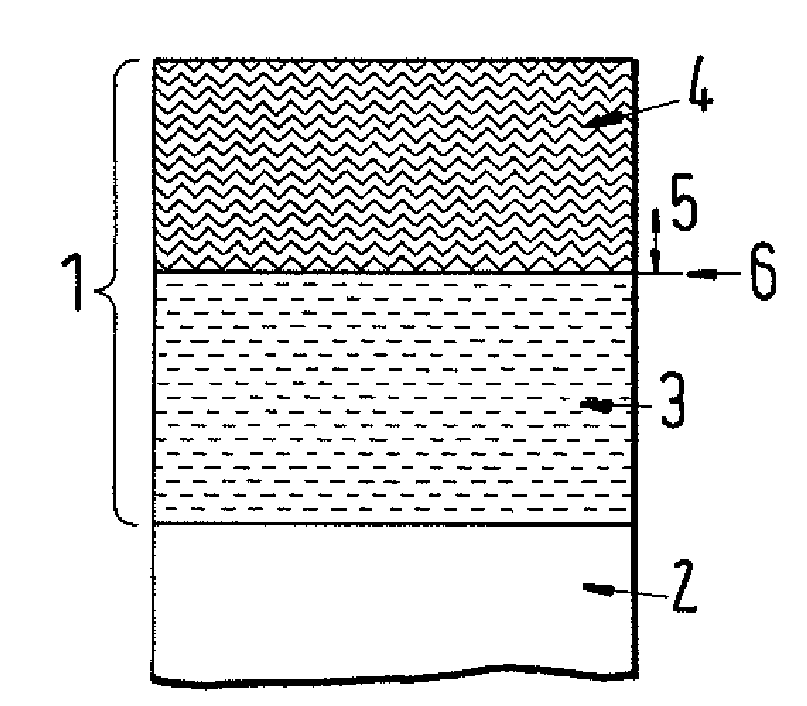
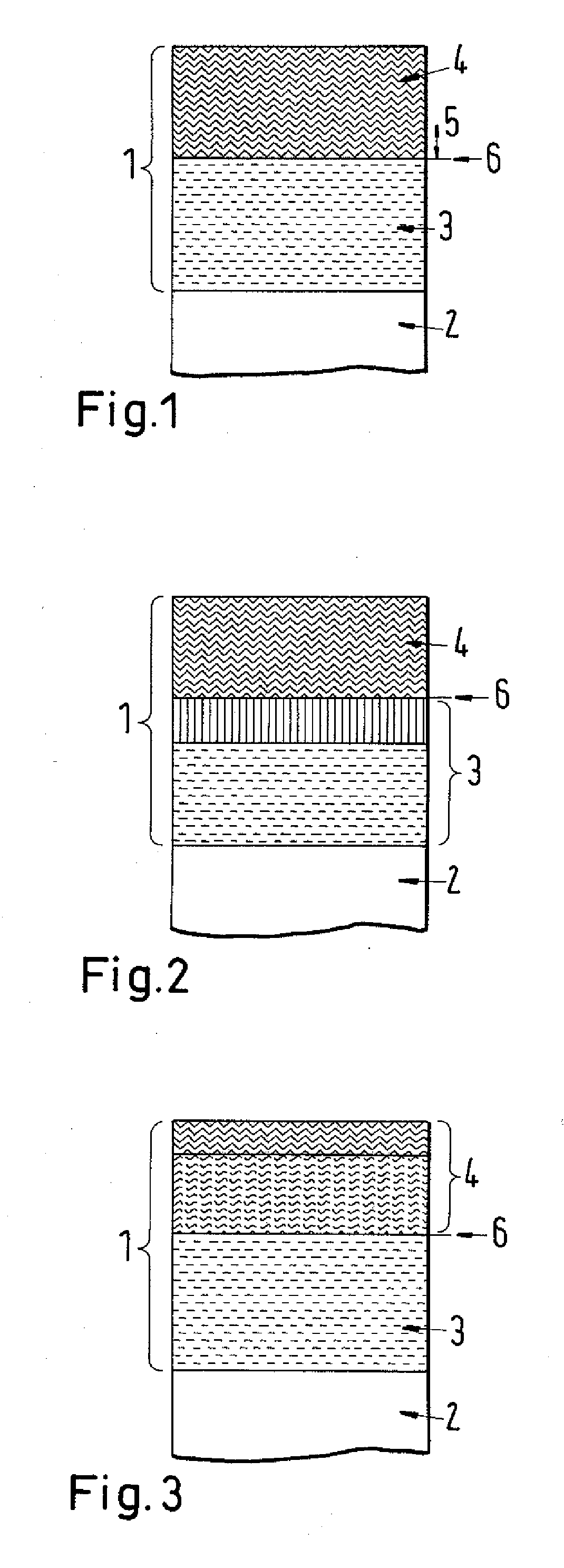
[0009]An object of the present invention is to provide a multilayer film-coated member which has both sufficient heat resistance and sufficient abrasion resistance and which has excellent coating film adhesion strength so that it can sufficiently exhibit the capability of the coating film even in cutting environments that may be more and more severe.
[0011]In the multilayer film-coated member of the invention, the ratio of the peak area X of B—O to the peak area Y of B—N, XY, as obtained from the peak separation of the is orbit of B in X-ray photoelectric spectrometry, may be X / Y≦0.2, within a range of at least 500 nm from the interface of the first composition hard coating film that is in contact with the underlying layer toward the surface of the first composition hard coating film. The oxygen distribution control in a specific region of the hard coating film remarkably improves the adhesion strength of the hard coating film having both excellent heat resistance and excellent abrasion resistance.

Problems solved by technology

However, the abrasion resistance of the film is not improved, and therefore it is difficult to apply the film to tools and slide members.
Accordingly, as compared with a TiAlN coating film, the (TiAl(SiC))N coating film has improved heat resistance and abrasion resistance, but since the base of the film is TiAlN, the effect of the improvement is limited.
For example, in the field of cutting work, the objects to be cut are being more difficult to cut and the working time is being much shortened for more rapid cutting speed and more rapid feeding of objects.
With these requirements, cutting tools are forced to be exposed too much severer working environments than before.

Method used


Image

  • Multilayer Film-Coated Member And Method For Producing It
  • Multilayer Film-Coated Member And Method For Producing It
  • Multilayer Film-Coated Member And Method For Producing It

Examples


examples

[0036]This is for evaluating the film properties of the hard coating film in the invention. Using a cemented carbide having a Co content of from 3% by weight to less than 12% by weight, a hard coating film was formed according to the following coating method.

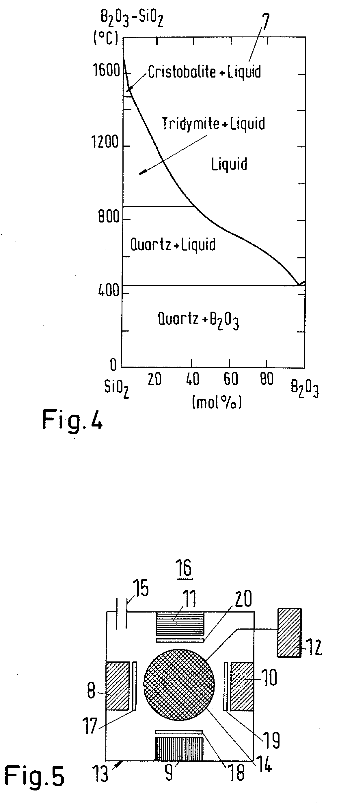
[0037]The first coating method comprises a first step of heating a tool at 500° C., a second step of ion cleaning for about 30 minutes by applying a pulse bias voltage having a negative voltage of 200 V, a positive voltage of 30 V, a frequency of 20 kHz and a pulse / pose 4 ratio of, a third step of coating with (AlTi)N by an arc source, a fourth step of coating with (AlTi)N by an arc source and washing the target surface by discharging the sputtering target while the shutter is shut, a fifth step of coating with SiBNCO by using a target having a molar blend ratio, BN / SiC of 1 / 3 in a mode of RF sputtering with an RF-coating source, and a sixth step of coating with SiBNCO by RF+DC by applying a DC bias having a negative voltage of ...


PUM

PropertyMeasurementUnit
thicknessaaaaaaaaaa
thicknessaaaaaaaaaa
thicknessaaaaaaaaaa

Abstract

The invention provides a multilayer film-coated member which has both sufficient heat resistance and sufficient abrasion resistance and has excellent coating film adhesion strength so that it can sufficiently exhibit the capability of the coating film even in cutting environments that may be more and more severe, and provides a method for producing it. The multilayer film-coated member is fabricated by coating the surface of a substrate with at least two hard coating films having different compositions, wherein the first composition hard film of the outermost layer of the hard coating films represented by SiaBbNcCdOe with a+b+c+d+e=1, 0.1≦a≦0.5, 0.01≦b≦0.2, 0.05≦c≦0.6, 0.1≦d≦0.7 and 0<e≦0.2, the second composition hard coating film of the lower layer below the first composition hard coating film is a hard film having at least two selected from Al, Ti, Cr, Ni, Ce, Mg, Nb, W, Si, V, Zr and Mo and N and at least one selected from B, C, and S and the oxygen content of the film within a range of at least 25 nm from the interface of the first composition hard coating film that is in contact with the underlying layer toward the surface of the first composition hard coating film is limited to a range of less than 3.5 atm. %. The method for producing the multilayer film-coated member comprises forming the first composition hard coating film under temperature control to keep the substrate temperature not higher than 400° C., and comprises forming it, after the coating target surface is cleaned through preliminary discharging, at a sputtering output power of less than 2500 W up to a thickness of at least 5 nm from the interface to the underlying layer.

Description

BACKGROUND OF THE INVENTION[0001]1. Field of the Invention[0002]The present invention relates to a multilayer film-coated member fabricated by forming a multilayer film on a substrate for abrasion-resistant members for cutting tools, molds and combustion engines or for members requiring heat resistance and abrasion resistance for airplanes, ground turbines, engines, gaskets, gears, pistons and others, and relates to a method for producing it.[0003]2. Background Art[0004]For the purpose of improving the heat resistance and abrasion resistance of coating films, development of various coating films is being promoted. With reference to typical cases of Patent References 1 to 3, described is one example of a process of development of coating films essentially for the purpose of improving the heat resistance and abrasion resistance of coating films. For the purpose of improving the heat resistance, many trials to coat heat-resistant materials have heretofore been made. For example, in Pat...

Claims


Application Information

Patent Timeline
Patent Type & Authority Applications(United States)
IPC IPC(8): B32B9/04C23C14/34C08K3/10F01D5/28
CPCC23C14/024C23C14/06Y10T428/2495C23C28/42Y10T428/265C23C28/042
Inventor VETTER, JORG
Owner SULZER METAPLAS
Why Eureka
Try Eureka