Needle structure and method of performing needle biopsies

a biopsies and needle technology, applied in the field of biopsy needles, can solve the problems of high false negative risk, high cost of x-ray imaging procedures, and inability to accurately detect the presence of cancer cells, and achieve the effect of small radiation distance, high energy density, and effective local tissue measuremen

Active Publication Date: 2010-02-04
CREO MEDICAL LTD
View PDF17 Cites 45 Cited by
  • Summary
  • Abstract
  • Description
  • Claims
  • Application Information

AI Technical Summary

Benefits of technology

[0009]The ability to measure dielectric properties of the tissue (the measured information) may offer significant advantage in terms of locating the cancerous tissue the first time the needle antenna is inserted into the region of tissue where it is suspected that a tumour is present, i.e. there may be no need to take a number of tissue samples. Also, the ability to measure tissue properties in this manner may reduce the risk of false negatives occurring.
[0053]a radioactive implant can be introduced accurately and the entrance channel can be controllably ablated to prevent seeding.

Problems solved by technology

There is a high risk of false negatives occurring when taking biopsies in this manner, and it may be necessary to perform several needle biopsies in the region where the lump has been felt in order for there to be a good chance of locating the cancerous tissue.
This form of image guidance has the obvious drawback of exposing the patient to potentially harmful doses of X-ray radiation.
Other drawbacks include: X-ray imaging procedures are expensive and can be time consuming, they require specialist support to drive the equipment, and they are not always successful in locating the cancerous site.
Needle biopsies are widely used and accepted as a safe and reliable test for the determination of the manifestation of cancer in the human body, but currently used methods may lead to cancerous cells being spread around the body when the biopsy needle is withdrawn.
This may lead to seeding and the development of new tumours.

Method used


Image

  • Needle structure and method of performing needle biopsies
  • Needle structure and method of performing needle biopsies
  • Needle structure and method of performing needle biopsies

Examples


Embodiment Construction

; FURTHER OPTIONS AND PREFERENCES

[0076]In this description the term ablation may refer to the ablation of a region of cancerous tissue, for example a tumour, or for sealing a track or channel made as the needle antenna passes through layers of healthy tissue. The latter will generally require lower levels of power and the track ablation may be performed with dynamic energy matching to the tissue impedance seen en route to ensure that controlled amounts of energy is launched into the various tissue types as the needle antenna traverses through the tissue to the outside world. However this invention need not be limited to performing controlled ablation with dynamic impedance matching being in place.

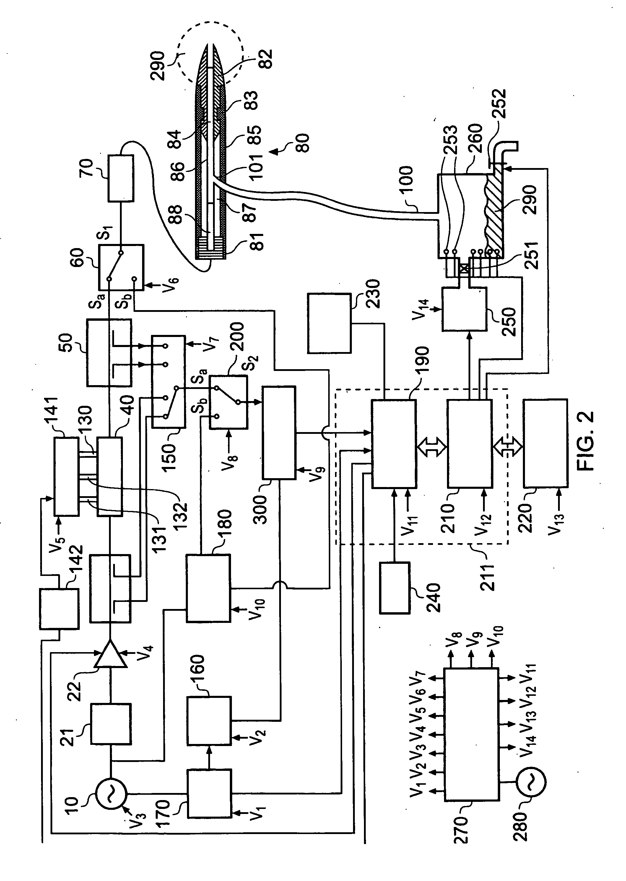
[0077]In general terms, one embodiment of the needle antenna structure comprises a rigid stainless steel structure with an outside diameter of around 2.2 mm and a sharp ceramic pointed cone at the distal tip to enable percutaneous insertion. However, the invention need not be limited to thi...


PUM


Abstract

A biopsy needle (80) having a longitudinal channel (84) formed within an inner conductor (86) of a coaxial antenna is disclosed. The coaxial antenna terminates in a rigid insertion tip (82) e.g. a ceramic cone that is insertable into biological tissue. Microwave energy (e.g. having a frequency of 1 to 100 GHz) delivered to the coaxial antenna is emitted at the insertion tip. The insertion tip may be arranged to match the impedance of the coaxial antenna to a predetermined tissue impedance. The emitted radiation can be used to measure properties of or treat (e.g. ablate) tissue at the insertion tip. Needle biopsy apparatus is also disclosed, in which a microwave energy is controllably delivered to a needle from a microwave generator. The apparatus may include an impedance tuner to dynamically match the impedance of the needle with tissue at the insertion tip.

Description

TECHNICAL FIELD[0001]The present invention relates to biopsy needles, i.e. needles adapted for the purpose of extracting fluid or cells (e.g. tissue) from the body e.g. for the purpose of identifying cancerous growths.BACKGROUND TO THE INVENTION[0002]A fine needle biopsy normally uses a thin hollow needle to remove a small tissue sample from an organ or a tumour. A common type of fine needle biopsy is a fine needle aspiration, where a fine needle and a syringe are used to remove either fluid from a cyst or clusters of cells from a solid mass. The procedure for fine needle aspiration and fine needle biopsy is basically the same, and the two procedures are sometimes performed together.[0003]Fine needle biopsies can be obtained from organs or tumours located within the human anatomy. Common sites that may be considered for biopsy procedures to be performed include: breasts, kidneys, the liver, the pancreas, the prostate, the thyroid, lungs, ovaries and lymph nodes. Fine needle biopsy i...

Claims


Application Information

Patent Timeline
Patent Type & Authority Applications(United States)
IPC IPC(8): A61B10/02
CPCA61B10/0233A61B10/0283A61B18/18A61B18/1815A61B18/1477A61B2018/1425A61B2018/183A61B2018/00636A61B2018/00875A61B2018/00642A61B10/04A61B2010/045A61B2018/1869A61B2018/1876A61B2018/1892A61B1/018A61B1/2676A61B1/307A61B5/0507A61B5/065A61B2018/00577A61B2018/00702A61B2018/00982A61M5/158A61N5/022A61N5/1007A61N2005/1024
Inventor HANCOCK, CHRISTOPHER PAUL
Owner CREO MEDICAL LTD
Why Eureka
Try Eureka