Method for filling through hole or non-through hole formed on board with filler

Inactive Publication Date: 2010-02-11
NAPRA
View PDF21 Cites 1 Cited by
  • Summary
  • Abstract
  • Description
  • Claims
  • Application Information

AI Technical Summary

Benefits of technology

[0007]An object of the invention is to provide a method capable of surely filling a filler in a t

Problems solved by technology

It has been noted that when an existing method represented by the method disclosed in Japanese Patent No. 3198273 or the like is appli

Method used


Image

  • Method for filling through hole or non-through hole formed on board with filler
  • Method for filling through hole or non-through hole formed on board with filler
  • Method for filling through hole or non-through hole formed on board with filler

Examples


Example

EXAMPLE 1

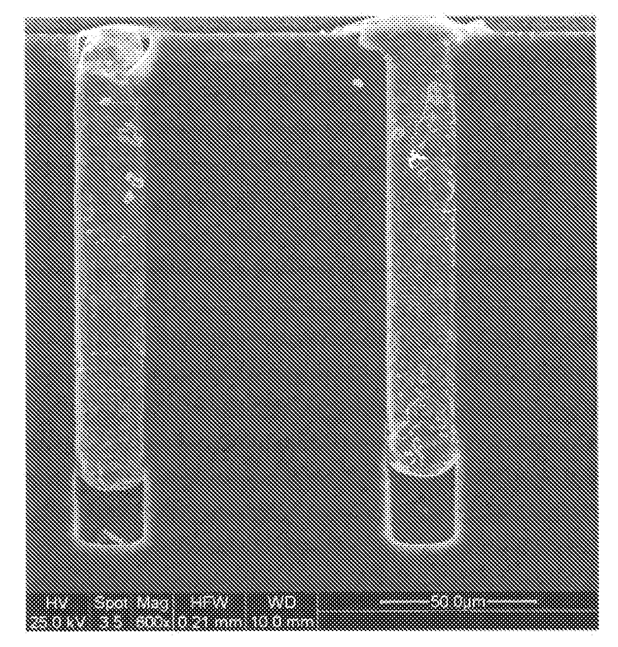
[0020]1,000,000 non-through holes having a diameter of about 23 μm, a hole depth of about 167 μm and an aspect ratio of about 7 were formed on a board configured of a 200 mm-thick wafer. A nanoparticulate paste was subjected to stencil printing while giving ultrasonic vibration (55 to 66 kHz) to this board. As the nanoparticulate paste, one containing a nanoparticle of gold (Au) as a major component and containing nanoparticles of bismuth (Bi), antimony (Sb) and gallium (Ga) was used. This nanoparticulate paste has a low melting point and when solidified, exhibits volume expansion properties to be caused due to properties of bismuth (Bi) (solidification expandable low-melting nanoparticulate paste). The ultrasonic vibration was also given to both a stencil and a squeeze. The ultrasonic vibration, however, may be given only to the stencil.

[0021]Subsequently, the board was rotated at a high speed (rotation number: 2,000 rpm) for 5 minutes while giving ultrasonic vibration (55...

Example

COMPARATIVE EXAMPLE 1

[0023]The same operations as in Example 1 were carried out without giving the ultrasonic vibration. This is designated as Comparative Example 1. A microscopic photograph of a cross-sectional surface of a sample obtained in Comparative Example 1 is shown in FIG. 2. The nanoparticulate paste was not completely filled to an extent of the bottom of the non-through hole, and a space remained in the bottom.

Example

EXAMPLE 2

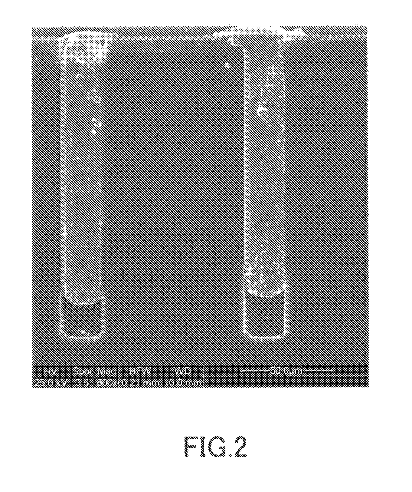
[0024]An operation for carrying out stencil printing and centrifugal filling while giving ultrasonic vibration was repeated twice, and a board was heated to solidify a nanoparticulate paste. This is designated as Example 2.

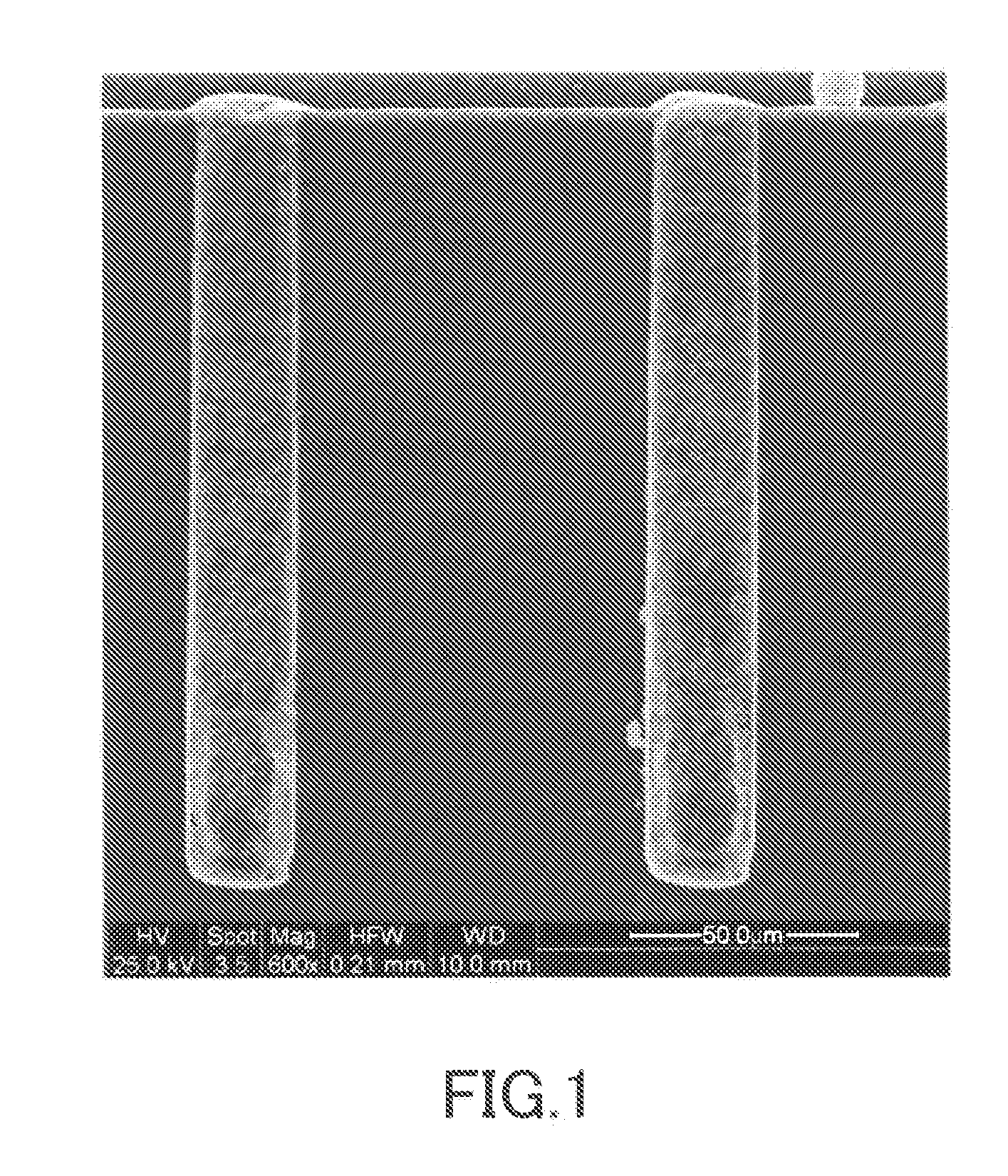
[0025]As a result of microscopic observation of a cross-sectional surface of a sample obtained in Example 2, the nanoparticulate paste is completely filled to an extent of the bottom of the non-through hole similar to the case of FIG. 1.


PUM

PropertyMeasurementUnit
Centrifugal forceaaaaaaaaaa
Viscosityaaaaaaaaaa
Magnetic forceaaaaaaaaaa

Abstract

A method for filling a through hole or a non-through hole formed on a board with a fluent filler comprises combining at least one filling method selected from a centrifugal filling method and a magnetic filling method with an ultrasonic filling method.

Description

BACKGROUND OF THE INVENTION[0001]1. Field of the Invention[0002]The present invention relates to a method for filling a through hole or a non-through hole formed on a board such as a multilayer circuit board or a wafer with a filler.[0003]2. Description of the Related Art[0004]It is publicly known to fill a throughhole or a non-through hole formed on a board such as a multilayer circuit board or a wafer with a liquid viscous material such as a nanoparticulate paste or an insulating resin paste. For example, Japanese Patent No. 3198273 discloses a method for filling a through hole or a non-through hole of a board with a liquid viscous material, wherein after stencil printing of the liquid viscous material on a circuit board in a vacuum atmosphere, the degree of vacuum of the vacuum atmosphere is lowered, or the vacuum atmosphere is turned to a usual atmospheric pressure atmosphere, thereby achieving differential pressure filling.[0005]The invention disclosed in Japanese Patent No. 31...

Claims


Application Information

Patent Timeline
IPC IPC(8): H05K3/40H05K3/00
CPCH05K3/4053H05K2201/083Y10T29/49165H05K2203/104H05K2203/1554H05K2203/0285
Inventor SEKINE, SHIGENOBUSEKINE, YURINAKUWANA, YOSHIHARU
Owner NAPRA
Why Eureka
Try Eureka