Excessive Pressure Release Valve And Release Valve Unit Having The Release Valve

a release valve and release valve technology, which is applied in the direction of cell components, cell component details, electrochemical generators, etc., can solve the problems of inability to use medical check valves as excessive pressure release valves for fuel cells, difficulty in providing uniform insertion openings for medical check valves, and inability to provide small and simpler safety valves. , to achieve the effect of accurately reliably and safely releasing an excessive pressure, small and simple structure, and excellent performan

Inactive Publication Date: 2010-02-11
ASAHI RUBBER
View PDF11 Cites 20 Cited by
  • Summary
  • Abstract
  • Description
  • Claims
  • Application Information

AI Technical Summary

Benefits of technology

[0030]The excessive pressure release valve of the present invention has an excellent performance in accurately reliably and safely releasing an excessive pressure widely ranging from a relatively low pressure of about 10 kPa to a pressure of about 2,000 kPa. The excessive pressure release valve is formed to be a small and simple structure and can be manufactured homogeneously, inexpensively and on a massive scale, thus being excellent in productivity. In addition, the excessive pressure release valve can be freely changed in design so as to fit thereof to the shape of the tank, the container or the piping whose internal pressure is to be adjusted. In addition, the excessive pressure release valve can be designed to work at an arbitrary pressure based on the

Problems solved by technology

However, with the development of recent downsizing technique in battery cells and home electric appliances, there is a demand for smaller and simpler safety valves that can surely and safely work at a relatively low excessive pressure and release the excessive pressure to the external world.
The medical check valve has a difficulty in providing a uniform insertion opening, without misalignment, at t

Method used


Image

  • Excessive Pressure Release Valve And Release Valve Unit Having The Release Valve
  • Excessive Pressure Release Valve And Release Valve Unit Having The Release Valve
  • Excessive Pressure Release Valve And Release Valve Unit Having The Release Valve

Examples


example 1

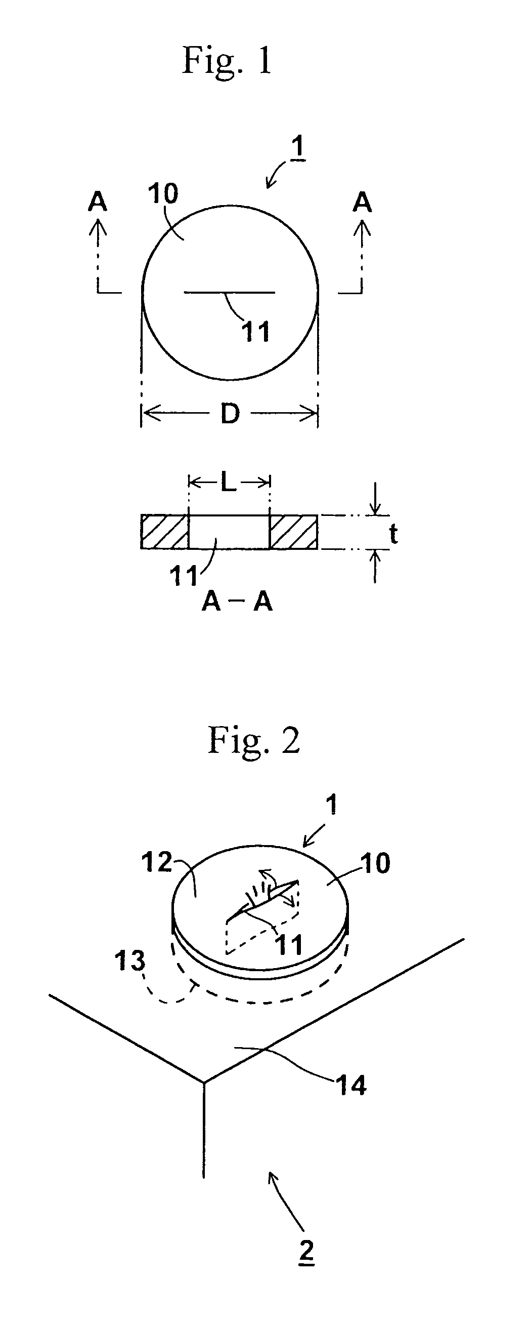
[0075]Disk-shaped elastic rubber plates 10 each having a diameter of 5 mm and a thickness of 0.5 mm were prepared. At around the center of each disk, a straight-lined slits 11 having an entire length of 1.6 mm was formed using a thin blade to obtain an excessive pressure release valve 1.

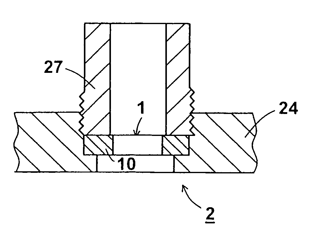
[0076]As shown in FIG. 5, the excessive pressure release valve 1 was clamped, at a compression ratio of some 25%, between an upper side clamp 20 having a through hole and a lower side clamp 21 that had a dent and a through hole formed at a central portion of the dent. Into the through hole of the lower side clamp 21, the excessive pressure release valve 1 placed on a level-raising ring-like spacer 22 having a thickness of 0.59 mm and a hole formed at its central portion, was fitted. A pressure of nitrogen gas having a pressure rising rate of 20 kPa / s was applied on the lower surface side of the excessive pressure release valve 1. The working pressure for the excessive pressure was determined by detec...

example 2

[0077]After producing the excessive pressure release valves 1 in the same manner as in Example 1, the working pressure to release the excessive pressure was determined in the same way as described in Example 1 except that the excessive pressure release valve 1 was clamped with a ring-like spacer 22 having a thickness of 0.50 mm and a hole formed at its central portion, at a compression ratio of about 10%. The results are shown in Table 3.

TABLE 3CompressionAssayWorkingDurometer AThicknessRatioTemperaturePressurehardness(mm)(%)(° C.)(kPa)A28 / S0.53623101A35S0.55923130A45 / S0.55923219A62 / S0.55923393A73 / S0.561123698

example 3

[0078]The excessive pressure release valves 1 provided with a slit 11 having an entire length of 2.0 mm were produced in the same way as described in Example 1. The working pressure to release the excessive pressure was determined in the same way as described in Example 1 except that the excessive pressure release valve 1 was clamped with a ring-like spacer 22 having a thickness of 0.50 mm and a hole at its central portion, at a compression ratio of about 10%. The results are shown in Table 4.

TABLE 4CompressionAssayWorkingDurometer AThicknessRatioTemperaturePressureHardness(mm)(%)(° C.)(kPa)A28 / S0.5362377A35S0.5592398A45 / S0.55923181A62 / S0.55923326A73 / S0.561123588


PUM


Abstract

Provided is a small, simple-structured, homogeneous and mass-producible excessive pressure release valve which works even at a relatively low excessive pressure to surely and safely release the pressure to the external world. The excessive pressure release valve has an elastic rubber plate and a reversibly openable slit that passes through the upper and the lower surfaces and release the pressure to the external world when the internal excessive pressure stressing on the lower side surface, pushes and opens the slit toward upper surface side. The elastic rubber plate is made of silicone rubber containing 1-20% by mass of silicone oil.

Description

TECHNICAL FIELD[0001]The present invention relates to an excessive pressure release valve having rubber elasticity that safely release an excessive internal pressure to the external world from sealed containers of a closed system such as fuel cells, electrolysis tanks of secondary cells, reaction vessels, storage containers etc. or sealed piping systems, and the present invention also relates to a release valve unit having such valve.BACKGROUND ART[0002]The secondary cells such as fuel cells, nickel-cadmium cells, nickel-hydrogen cells, lithium-ion cells, lead batteries etc. are used for power supplies of automobiles or portable electronic devices and home electric appliances such as cell-phones, laptop personal computers, and so on.[0003]These cells each have a safety valve to automatically release a pressure to the external world when an internal pressure becomes excessively high.[0004]For example, Japanese Unexamined Patent Publication No. JP 0547363A discloses a sealed-type seco...

Claims


Application Information

Patent Timeline
IPC IPC(8): F16K15/14
CPCH01M2/1229H01M2/1294H01M8/02Y02E60/50H01M8/04201H01M8/2465H01M8/04082H01M50/325H01M50/342Y02E60/10Y10T137/7879Y10T137/7881Y10T137/7888
Inventor NEMOTO, MASASHIYAGINUMA, YUKIOYAMASHITA, TAKEO
Owner ASAHI RUBBER
Why Eureka
Try Eureka