Tiime gated fluorescent flow cytometer

a flow cytometer and fluorescent technology, applied in the field of tiime gated fluorescent flow cytometers, can solve the problems of reducing the visibility of fluorescent markers, spectral selection techniques are useful, and fluorescent markers can lose much of their discriminatory power

Inactive Publication Date: 2010-02-11
MACQUARIE UNIV
View PDF23 Cites 36 Cited by
  • Summary
  • Abstract
  • Description
  • Claims
  • Application Information

AI Technical Summary

Benefits of technology

[0012]Preferably the apparatus includes a condenser lens for collecting the stimulating light. More preferably the apparatus includes another spatial filter for spatially filtering the stimulating light. Still more preferably the apparatus includes a wavelength selective filter for filtering the stimulating light. Yet still more preferably the apparatus includes a dichroic mirror for reflecting the stimulating light. Even still more preferably the apparatus includes an objective lens for focussing the stimulating light.
[0013]Preferably the apparatus includes an objective lens for collecting the fluorescent light. More preferably the spatial filter is at an image plane of the objective lens for collecting the fluorescent light. Even more preferably the detector is an optical band limited detector. Still more preferably the optical band limited detector includes an optical pass band filter for passing the fluorescent light.

Problems solved by technology

Fluorescence techniques can provide exquisite sensitivity, however fluorescent markers can lose much of their discriminatory power when viewed in the presence of autofluorescence.
Organic and inorganic autofluorophores are in nature and some materials fluoresce with great intensity, diminishing the visibility of fluorescent markers.
Spectral selection techniques are useful in suppressing these unwanted sources of interference but by themselves are not always sufficient because of the abundance and spectral range of autofluorophores.
Less than 1% of microorganisms found in the environment respond to culture and the detection of rare organisms using conventional fluorescent techniques can be exceptionally difficult.
However, choppers have an inflexible pulse regime, waste light and potentially give image blur arising from drive motor vibration.
However the low repetition rate of N2 lasers (10-60 Hz) is a significant detraction and their rapid high voltage discharge radiates an intense electromagnetic pulse that can cause instrumentation problems.
Although their capital cost is intermediate, these laser sources are very inefficient and the modulator adds further to the costs.
Gas discharge lasers require substantial electrical power input and generate significant heat that must be dissipated.
Gas discharge laser excitation systems are bulky, expensive and relatively unreliable.
To monitor disease progression in HIV / AIDS patients, absolute CD4+ and CD8+ T cell counts are typically required to be tested every 3 months for every patient, however, due to the operational cost and complexity of regular flow cytometry testing of blood, only 0.25% of HIV infected patients, in South Africa for example, are tested according to a recent report.

Method used


Image

  • Tiime gated fluorescent flow cytometer
  • Tiime gated fluorescent flow cytometer
  • Tiime gated fluorescent flow cytometer

Examples


Embodiment Construction

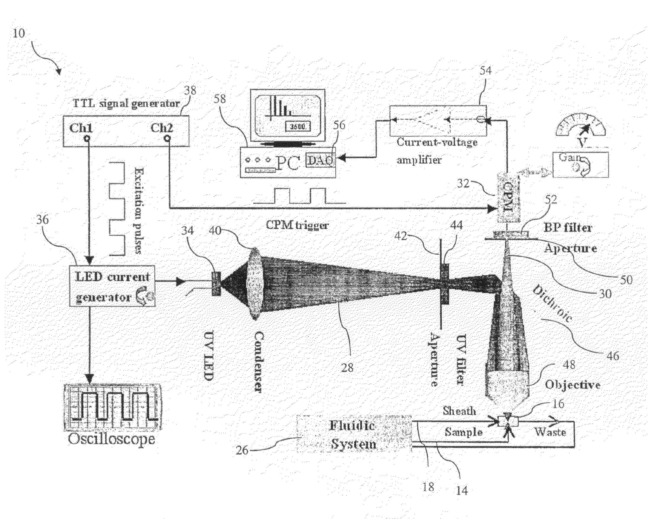
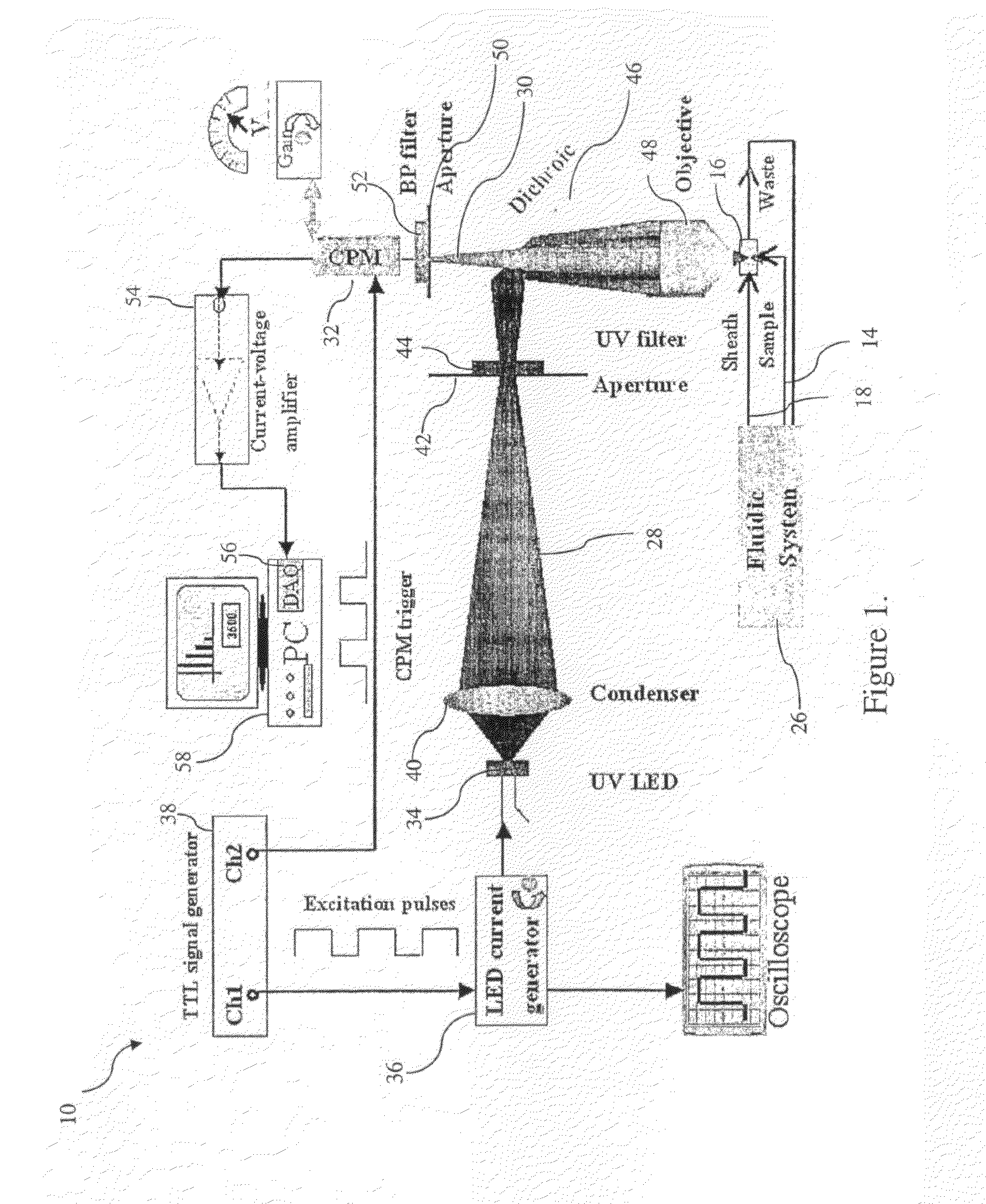
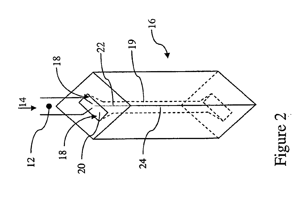
[0058]FIG. 1 depicts one embodiment of an apparatus 10 for detecting a particle labelled with a fluorescent marker. As shown in FIG. 2, the particle 12 is suspended in a sample fluid 14 that is injected into a capillary 19 of a flow cell 16 for interrogation. A sheath fluid 18 is simultaneously injected into the capillary 19, in an annular region 20 around the injected sample fluid 14. The small diameter of the capillary 19 ensures that the sheath fluid 18 flow is laminar. The sheath fluid 18 hydrodynamically focuses the sample fluid 14 into a thin fluid channel 22 along the axis of the capillary 19 lining up the particle 12. In this embodiment, the flow cell 16 is made of an ultraviolet transparent optical material such as quartz. The capillary 19 has an internal cross section of 430 micrometres by 180 micrometres. The flow of the sample 14 and sheath 18 fluids is promoted by a fluid vacuum pump 26. In this embodiment, the fluid flow is 15.6 millilitres per minute and 166 microlitr...


PUM

PropertyMeasurementUnit
fluorescence lifetimeaaaaaaaaaa
velocityaaaaaaaaaa
poweraaaaaaaaaa

Abstract

An apparatus (10) for detecting a particle (12) labelled with a fluorescent marker is disclosed. The apparatus (10) has a flow cell (16) being adapted to contain a fluid (14) in which the particle (12) is suspended. A light source (28) is operatively coupled to the flow cell (16) and arranged for emitting a stimulating light (28) which is effective in optically exciting the fluorescent marker (12) for emitting a fluorescent light (30). The apparatus (10) also includes a spatial filter (50) across an optical path between the particle (12) and a time gated detector (32) operatively coupled to the flow cell (16) for detecting the fluorescent light (30).

Description

FIELD OF THE INVENTION[0001]The invention relates broadly to an apparatus for detecting a particle labelled with a fluorescent marker, the particle being suspended in a fluid.BACKGROUND OF THE INVENTION[0002]Flow cytometry is a technique to quickly count and sort cells, biomolecules, viruses, cells, protozoa, bacteria, micro particles or other particles suspended in a fluid. The fluid containing the particles is passed through a flow cell through which a beam of light, typically a laser beam, passes. In one embodiment of flow cytometry the laser light is scattered by a particle in the flow cell and the scattered light is detected. The number of particles that have passed through the flow cell can thus be counted, sized and sorted. In another embodiment, the particles are first labelled with a fluorescent marker. A beam of light excites the fluorescent marker and the resulting fluorescent light is detected for counting of the particles. Flow cytometry finds numerous applications incl...

Claims


Application Information

Patent Timeline
Patent Type & Authority Applications(United States)
IPC IPC(8): G01N21/64G01J1/58
CPCG01N15/14G01N15/1436G01N15/1434
Inventor DAYONG, JINPIPER, JIMCONNALLY, RUSSELL
Owner MACQUARIE UNIV
Why Eureka
Try Eureka