Deformable mirror, mirror apparatus, and exposure apparatus

a mirror and surface technology, applied in the field of deformation mirrors, can solve the problems of difficult to finely correct the shape of the surface (surface shape) of the mirror, vibration of the cooling mechanism might be transmitted to the mirror, and the conventional mirror-deformation mechanism is considerably large-scale. achieve the effect of efficiently cooling the mirror and finely correcting the surface shape of the mirror

Inactive Publication Date: 2010-02-11
NIKON CORP
View PDF6 Cites 39 Cited by
  • Summary
  • Abstract
  • Description
  • Claims
  • Application Information

AI Technical Summary

Benefits of technology

[0019]According to the present invention, by providing the thin film-shaped piezoelectric elements in the plurality of areas on the back surface of the mirror, it is possible to finely correct the surface shape of the mirror as compared with any conventional mirror-de

Problems solved by technology

Therefore, the conventional mirror-deforming mechanism is considerably large-sized.
However, the conventional mirror-deforming mechanism is the large-sized mechanism, and hence it is impossible to arrange, on the back surface of the mirror, the mirror-deforming mechanisms of a number which is la

Method used


Image

  • Deformable mirror, mirror apparatus, and exposure apparatus
  • Deformable mirror, mirror apparatus, and exposure apparatus
  • Deformable mirror, mirror apparatus, and exposure apparatus

Examples


Embodiment Construction

[0027]An exemplary embodiment of the present invention will be explained with reference to FIGS. 1 to 4 by way of example.

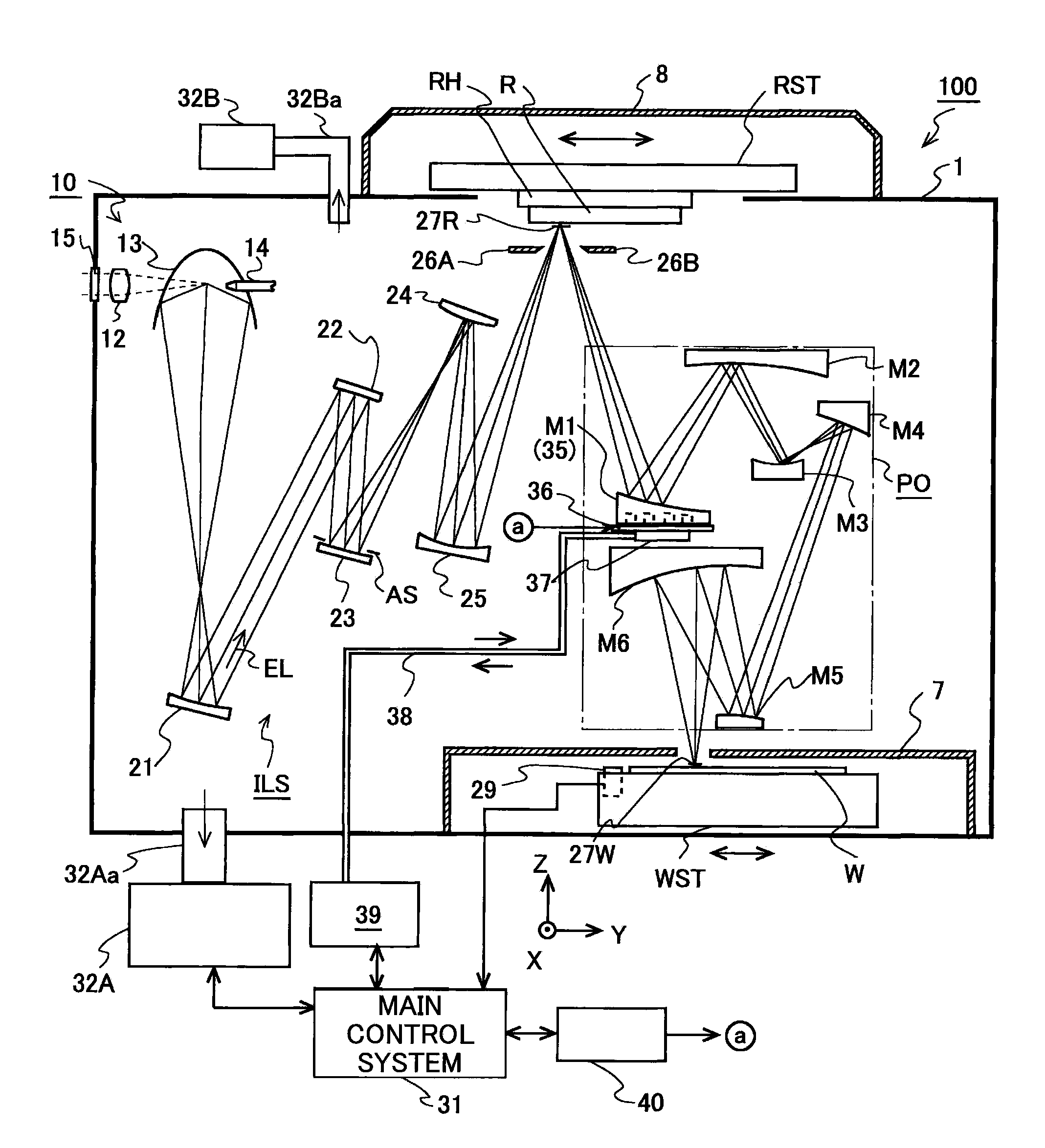
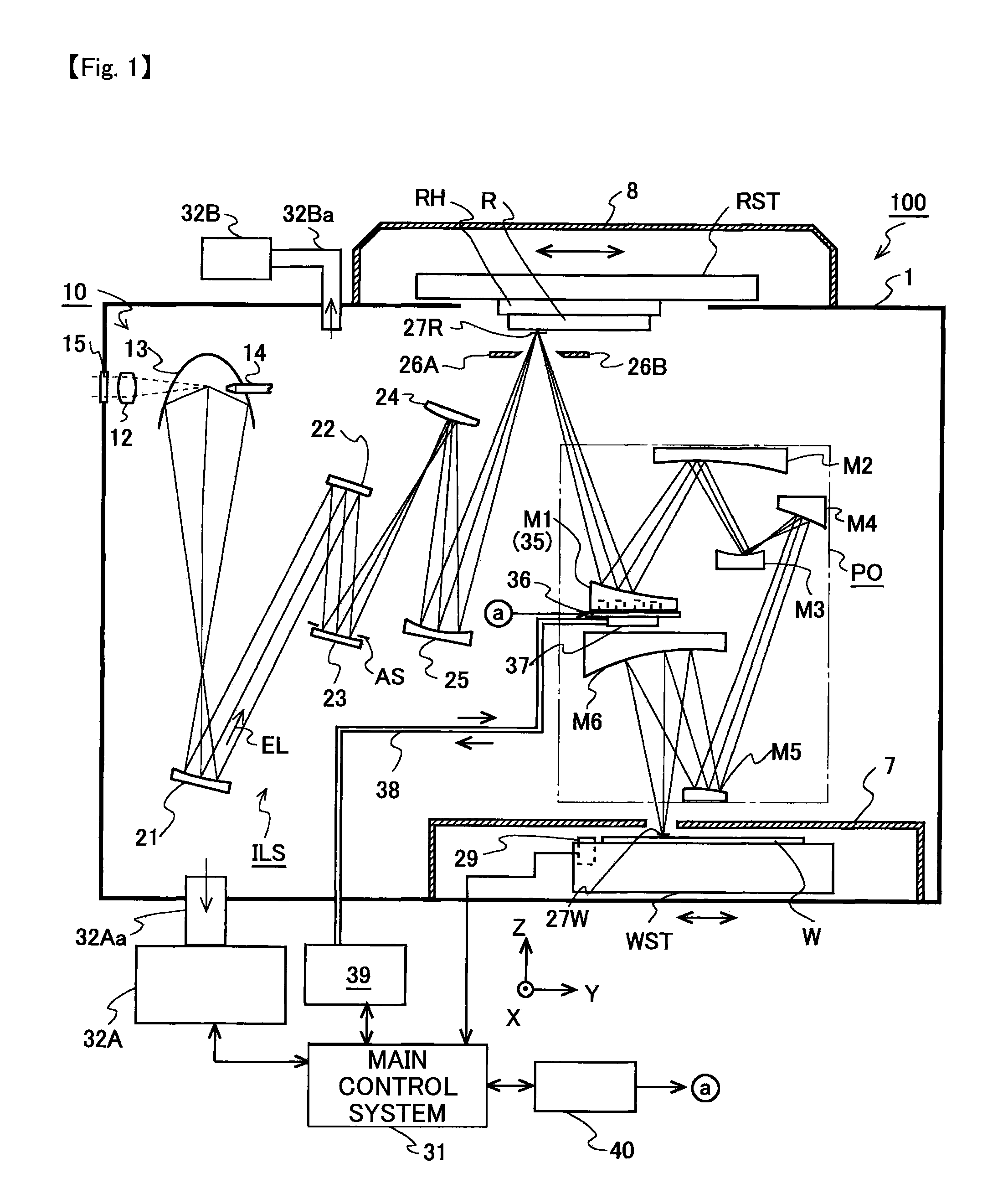
[0028]FIG. 1 is a sectional view schematically illustrating the overall construction of an exposure apparatus (EUV exposure apparatus) 100 of this embodiment which uses, as an exposure light EL (illumination light or illumination light beam), a EUV light (Extreme Ultraviolet Light) (EUV light beam) having a wavelength of not more than 100 nm, for example, 11 nm or 13 nm within a range of, for example, about 3 to 50 nm. With reference to FIG. 1, the exposure apparatus 100 includes a laser plasma light source 10 which generates the exposure light EL, an illumination optical system ILS which illuminates a reticle R (mask) with the exposure light EL, a reticle stage RST which is movable while holding the reticle R, and a projection optical system PO which projects an image of a pattern formed on a pattern surface (reticle surface) of the reticle R onto a wafer W (pho...


PUM


Abstract

A mirror apparatus includes a plurality of holes which are divided by partition wall portions on a back surface of a mirror, a plurality of thin film piezoelectric elements which are fixed to bottom surfaces of the plurality of holes respectively, a radiation temperature-regulating plate which has a plurality of projections inserted into the holes, and a mirror control system which individually controls voltages to be applied to the plurality of thin film piezoelectric elements to deform the mirror. The mirror can be efficiently deformed and/or cooled from the side of the back surface without transmitting any vibration to the mirror.

Description

CROSS-REFERENCES TO RELATED APPLICATIONS[0001]This application claims the benefit of priority of U.S. Provisional Application No. 61 / 136,074 filed on Aug. 11, 2008, the entire disclosures of which are incorporated herein by reference.BACKGROUND OF THE INVENTION[0002]1. Field of the Invention[0003]The present invention relates to a deformable mirror, a mirror apparatus, and an exposure technique and a device-producing technique using the mirror apparatus.[0004]2. Description of the Related Art[0005]For example, when a semiconductor device or the like is produced, an exposure apparatus is used in order that a pattern, which is formed on a reticle (or a photomask or the like), is transferred onto a wafer (or a glass plate or the like) coated with a resist to perform the exposure. Recently, in order to further enhance the resolution, an exposure apparatus (hereinafter referred to as “EUV exposure apparatus”) has been also developed, which employs, as the exposure light (exposure light b...

Claims


Application Information

Patent Timeline
IPC IPC(8): G03B27/72G02B7/182
CPCG02B17/0663G02B26/0825G21K1/06G03F7/70266G03F7/70891G02B26/0858
Inventor SHIRAISHI, MASAYUKI
Owner NIKON CORP
Why Eureka
Try Eureka