

Image encoding apparatus and method of controlling the same
a technology of image encoding and control apparatus, which is applied in the field of image encoding technique, can solve the problems of low encoding efficiency, low encoding efficiency, and long process time of the method for re-encoding, and achieve the effect of reproducing a high-quality image in a short process time and small memory capacity
- Summary
- Abstract
- Description
- Claims
- Application Information
AI Technical Summary
Benefits of technology
Problems solved by technology
Method used
Image

Examples
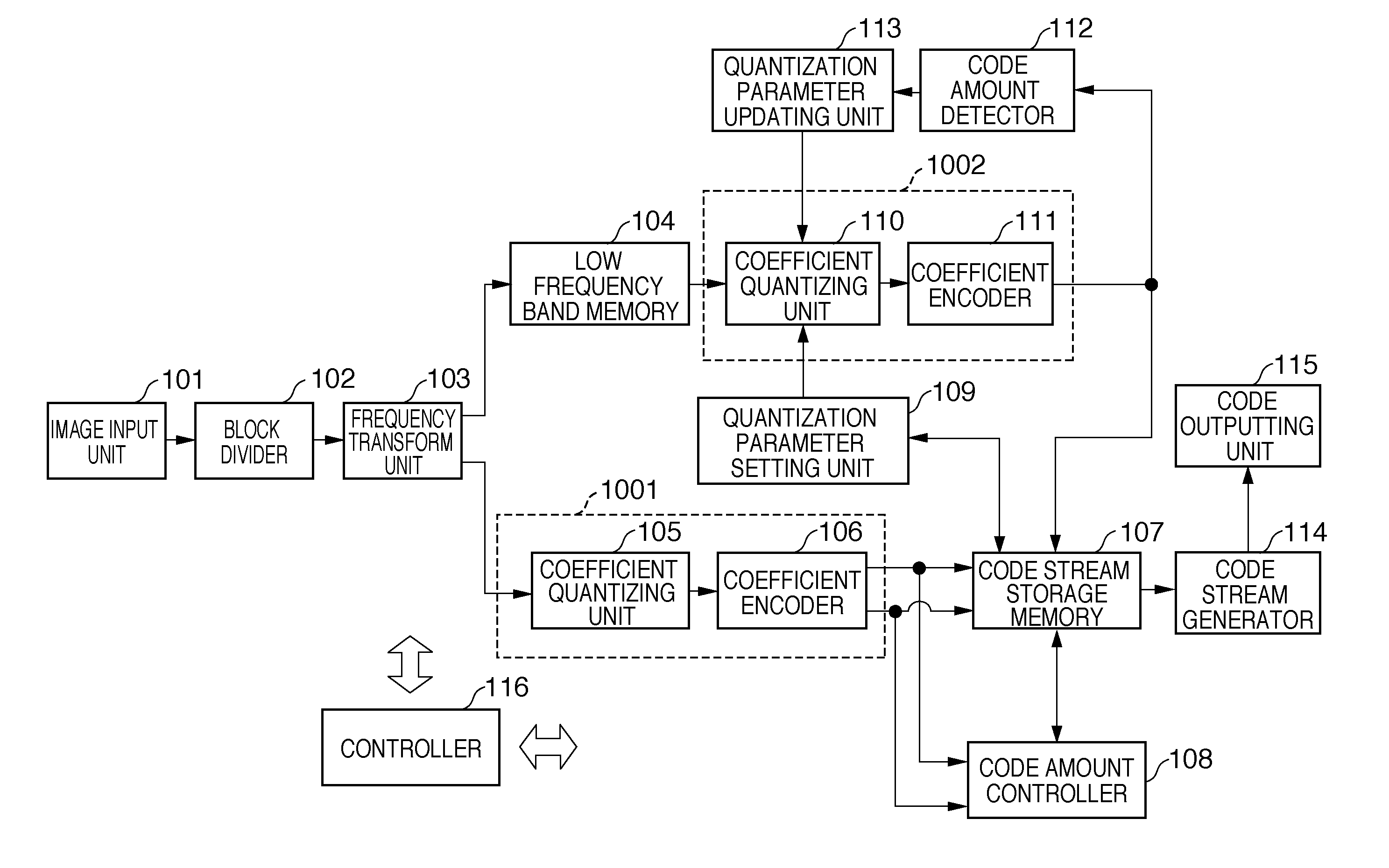
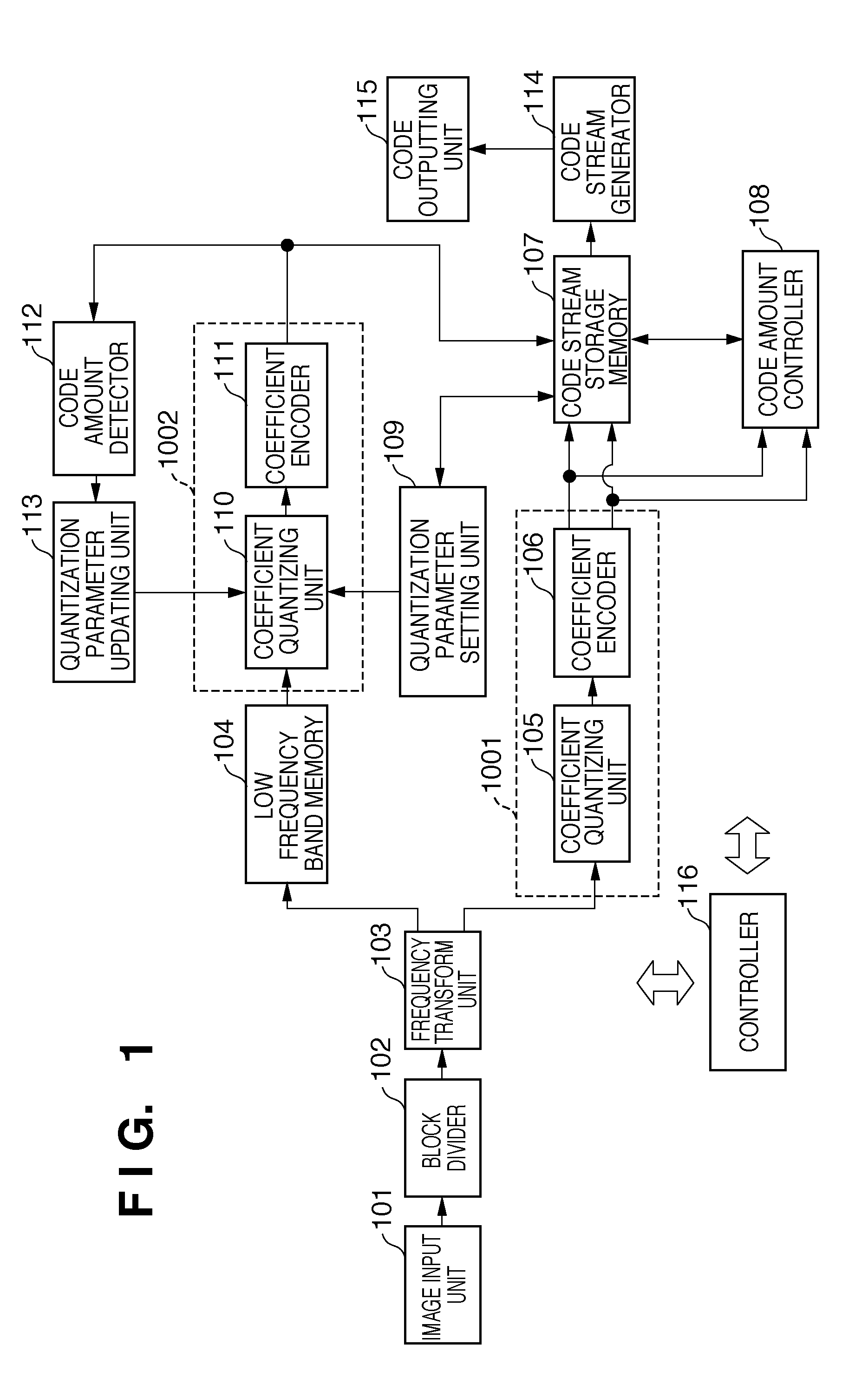
first embodiment
Modification of First Embodiment
[0131]A modification of the first embodiment will be described below, which implements the same processing as in the first embodiment by a computer program read out and executed by a computer.
[0132]FIG. 14 is a block diagram showing the arrangement of an information processing apparatus (e.g., personal computer) according to the modification.
[0133]Referring to FIG. 14, a CPU 1401 controls the entire apparatus and executes image encoding processing and decoding processing to be described later using programs and data stored in a RAM 1402 or a ROM 1403. The RAM 1402 has an area to store programs and data read out from an external storage device 1407 or a storage medium drive 1408 or downloaded from an external device via an I / F 1409. The RAM 1402 also has a work area to be used by the CPU 1401 to execute various kinds of processing. The ROM 1403 stores a boot program, the setting program of the apparatus, and data. A keyboard 1404 and a mouse 1405 can i...
second embodiment
[0154]In the first embodiment and its modification, image data is separated into low frequency band data and high frequency band data, and the high frequency band data is encoded first. After that, the low frequency band data is encoded by setting the quantization parameter of the low frequency band based on the code amount of the high frequency band data and repeatedly adjusting the quantization parameter such that the code amount falls within the range of the target code amount. However, the process time for re-encoding may pose a problem if, for example, it is necessary to encode many images within a predetermined time.
[0155]As the second embodiment, an embodiment preferable for, e.g., a digital camera capable of switching between a single shooting mode and a continuous shooting mode will be described. In the single shooting mode without strict restriction of time for encoding processing of one image, low frequency band data is re-encoded as needed, as in the first embodiment. On...
third embodiment
[0175]In the second embodiment, the code amount control method is switched in accordance with the image shooting mode. However, the method can also be switched based on any other information. In the third embodiment, an example will be described in which the code amount control method is switched based on the size of an image to be taken.
[0176]The operation of the third embodiment is different from that of the second embodiment only in the method of setting the operation mode signal to be input to the controller.
[0177]An image encoding apparatus according to the third embodiment encodes three kinds of images which have different numbers of horizontal and vertical pixels. The images will be referred to as S, M, and L in ascending order of size. For L, i.e., if the resolution is high, the number of pixels that undergo the encoding processing is large. This requires a process time longer as compared to S and M and makes degradation in the high frequency band unnoticeable. Conversely, a...
PUM
 Abstract
Description
Claims
Application Information