Controller for motor, and vehicle

a technology for controlling devices and vehicles, applied in the direction of gas pressure propulsion mounting, electric devices, emergency protective arrangements for automatic disconnection, etc., can solve the problems of short-circuit failure and excess electric current flow, and achieve the effect of excess curren

Inactive Publication Date: 2010-02-11
HONDA MOTOR CO LTD
View PDF8 Cites 69 Cited by
  • Summary
  • Abstract
  • Description
  • Claims
  • Application Information

AI Technical Summary

Benefits of technology

[0025]In other words, in the vehicle provided with the motor used as the driving force generation element of the vehicle, even though a power distribution control is not performed on the motor, the output shaft of the motor will be driven to rotate by the kinetic energy or the engine of the vehicle. Consequently, an electromotive force occurs in the armatures of each phase of the motor. Therefore, by providing the conductive plate member in each arm

Problems solved by technology

When the motor is in operation, a short-circuit failure may occur in either switch portion of the inverter circuit so that the switch portion is kept in a continual conducted state despite a control signal output to a switch element of the switch portion.
Moreover, a short-circuit failure state of the switch portion means that the switch element of the switch portion is switched on (conducted state) continuously despite a control signal output to the switch element, or a feedback diode is in the conducted state in both directions, namely, a forward direction and a backward

Method used


Image

  • Controller for motor, and vehicle
  • Controller for motor, and vehicle
  • Controller for motor, and vehicle

Examples


first embodiment

[0034]the present invention will be described in detail with reference to FIG. 1 to FIG. 7.

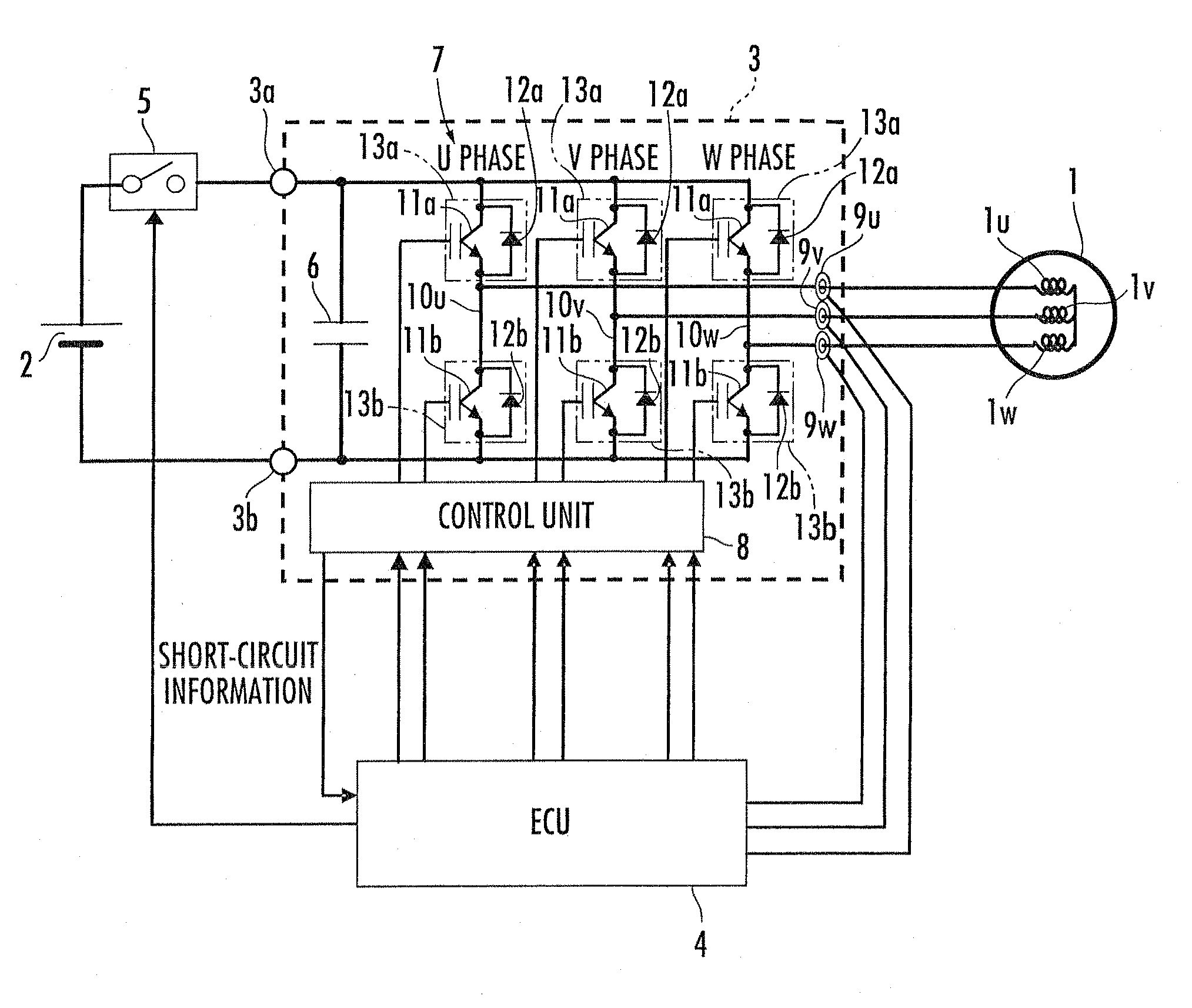
[0035]Illustrated in FIG. 1 is a circuit configuration of a controller of a motor in the first embodiment. In FIG. 1, the reference numeral 1 denotes a motor, the reference numeral 2 denotes a capacitor used as a direct-current power source for the motor 1, the reference numeral 3 denotes a power drive circuit unit (hereinafter, referred to as PDU) of the motor 1, and the reference numeral 4 denotes an electronic control unit (hereinafter, referred to as ECU) for performing an operation control on the motor 1 through the intermediary of the power drive circuit unit 3.

[0036]The motor 1 is a 3-phase brushless DC motor, for example. In the present embodiment, the motor 1 is mounted in a hybrid vehicle of a parallel type (not shown) as an auxiliary driving force generation element. It is also acceptable to mount the motor 1 in an electric vehicle or in a hybrid vehicle of a series type (not shown)...

second embodiment

[0046]According to the control processing in FIG. 3 described above, when a short-circuit failure occurs to bring either of the switch portions 13 into the conducted state, the switch elements 11 of the other two normal switch portions 13 on the same polarity side as the short-circuit failure switch portion 13 are controlled to be kept in the ON state finally. Thereby, the short-circuit failure switch portion 13 and all the other switch portions 13 on the same polarity side as the short-circuit failure switch portion 13 are brought into the conducted state, and meanwhile, all the switch elements on the different side from the short-circuit failure switch portion 13 are controlled to be in the OFF state. Therefore, for each arm 10 of the inverter circuit 7, the switch portions 13 at the same polarity side as the short-circuit failure switch portion 13 (the parallel circuit composed of the switch elements 11 and the feedback diodes 12) are in the conducted state in both directions. Fo...


PUM


Abstract

When a short-circuit failure of any of switch portions (13) including switch elements (11) and parallel-connected feedback diodes (12) of an inverter circuit (7) is detected during the operation of a motor (1), a switch portion (13) where the short-circuit failure has occurred is checked for whether it is on the positive polarity side or the negative polarity side. The switch elements (11) are so controlled that all the switch portions (13) on the same polarity side as where the short-circuit has occurred are brought into a conducted state and all the others disconnected. This prevents a large electric current from flowing into each switch portion of the inverter circuit without requiring any switch to block the power distribution between a motor and the inverter circuit when a short-circuit failure of the switch portion of the inverter circuit occurs.

Description

BACKGROUND OF THE INVENTION[0001]1. Field of the Invention[0002]The present invention relates to a controller for a motor used as a driving force generation element or the like for a vehicle, and a vehicle mounted with the motor.[0003]2. Description of the Related Art[0004]Generally, a motor having an armature of multiple phases, such as a brushless direct-current motor of three phases, is mounted in a vehicle such as a hybrid vehicle or an electric vehicle and is used as a driving force generation element for the vehicle. The operation control of the motor is generally performed by supplying electric power from a capacitor such as a battery or the like through the intermediary of an inverter (PWM inverter) circuit of multiple phases to the motor (for example, refer to Japanese Patent Laid-open No. H9-46811).[0005]In general, the inverter circuit designated by a reference number 7 has a circuit configuration illustrated in FIG. 1, for example. As illustrated, the inverter circuit 7 ...

Claims


Application Information

Patent Timeline
IPC IPC(8): B60L3/04G06F19/00G01R31/02H02H7/08H02M7/48H02P6/06H02P6/08H02P6/12H02P6/28H02P21/22H02P23/07H02P27/06H02P27/08
CPCB60L3/003B60L3/0069B60L3/04B60L11/1803Y02T10/7005G01R31/42H02P29/022Y02T10/642G01R31/025H01L2224/40137H01L2224/40139H01L2224/40225H01L24/40H01L2924/13055H02P29/032H01L2224/84801H01L2224/37147H01L2224/83801H01L24/37H01L2224/37599B60L50/51G01R31/52Y02T10/64Y02T10/70H01L24/84H01L2924/00H01L2924/00014
Inventor HOSODA, MASAHARUSAITO, YUJIDANJO, YASUYUKIINOUE, HIDEKISUGIYAMA, TETSUKATO, JUNJI
Owner HONDA MOTOR CO LTD
Why Eureka
Try Eureka