Power output apparatus, internal combustion engine system, and control methods thereof

Inactive Publication Date: 2010-02-11
TOYOTA JIDOSHA KK
View PDF6 Cites 12 Cited by
  • Summary
  • Abstract
  • Description
  • Claims
  • Application Information

AI Technical Summary

Benefits of technology

[0020]According to anther aspect, the present invention is directed to a control method of a power output apparatus that is constructed to output power to a driveshaft and includes: an internal combustion engine connected with the driveshaft in such a manner as to be rotatable independently of the driveshaft and to transmit part of an output power to the driveshaft and equipped with a catalytic converter that is filled with a catalyst having high oxygen storage capacity to reduce the toxicity of exhaust gas; and a rotation speed adjustment structure designed to adjust a rotation speed of an output shaft of the internal combustion engine. The control method including the steps of: under active rotation speed reduction control that controls the internal combustion engine and the rotation speed adjustment structure to lower the rotation speed of the output shaft of the internal combustion engine in an accelerator-off state, controlling the internal combustion engine to stop fuel injection to the internal combustion engine and to increase an amount of intake air to the internal combustion engine, and on resumption of the fuel injection to the internal combustion engine after the active rotation speed reduction control, controlling the internal combustion engine to resume the fuel injection to the internal combustion engine with a resumption-time fuel injection amount, which is increased from a standard fuel injection amount in a steady operation of the internal combustion engine relative to the amount of intake air to the internal combustion engine, while under passive rotation speed reduction control that controls the internal combustion engine and the rotation speed adjustment structure to lower the rotation speed of the output shaft of the internal combustion engine without adjustment of the rotation speed of the output shaft of the internal combustion engine by the rotation speed adjustment structure in the accelerator-off state, controlling the internal combustion engine to stop the fuel injection to the internal combustion engine and to increase the amount of intake air to the internal combustion engine, and on resumption of the fuel injection to the internal combustion engine after the passive rotation speed reduction control, controlling the internal combustion engine to resume the fuel injection to the internal combustion engine with a smaller fuel injection amount than the resumption-time fuel injection amount.
[0021]Under the active rotation speed reduction control that controls the internal combustion engine and the rotation speed adjustment structure to lower the rotation speed of the output shaft of the internal combustion engine in the accelerator-off state, the control method according to this aspect of the invention controls the internal combustion engine to stop the fuel injection to the internal combustion engine and to increase the amount of intake air to the internal combustion engine. Such engine control effectively reduces the potential smell given by the catalyst. On resumption of the fuel injection to the internal combustion engine after the active rotation speed reduction control, the control method controls the internal combustion engine to resume the fuel injection to the internal combustion engine with the resumption-time fuel injection amount, which is increased from the standard fuel injection amount in the steady operation of the internal combustion engine relative to the amount of intake air to the internal combustion engine. The control of the rotation speed adjustment structure promptly lowers the rotation speed of the internal combustion engine and thereby decreases the amoun

Problems solved by technology

Resumption of the fuel injection with the increased amount of the fuel supply than that of the stoichiometric air-fuel ratio in combination with the increased amount of the intake air for reduction of the

Method used


Image

  • Power output apparatus, internal combustion engine system, and control methods thereof
  • Power output apparatus, internal combustion engine system, and control methods thereof
  • Power output apparatus, internal combustion engine system, and control methods thereof

Examples


Example

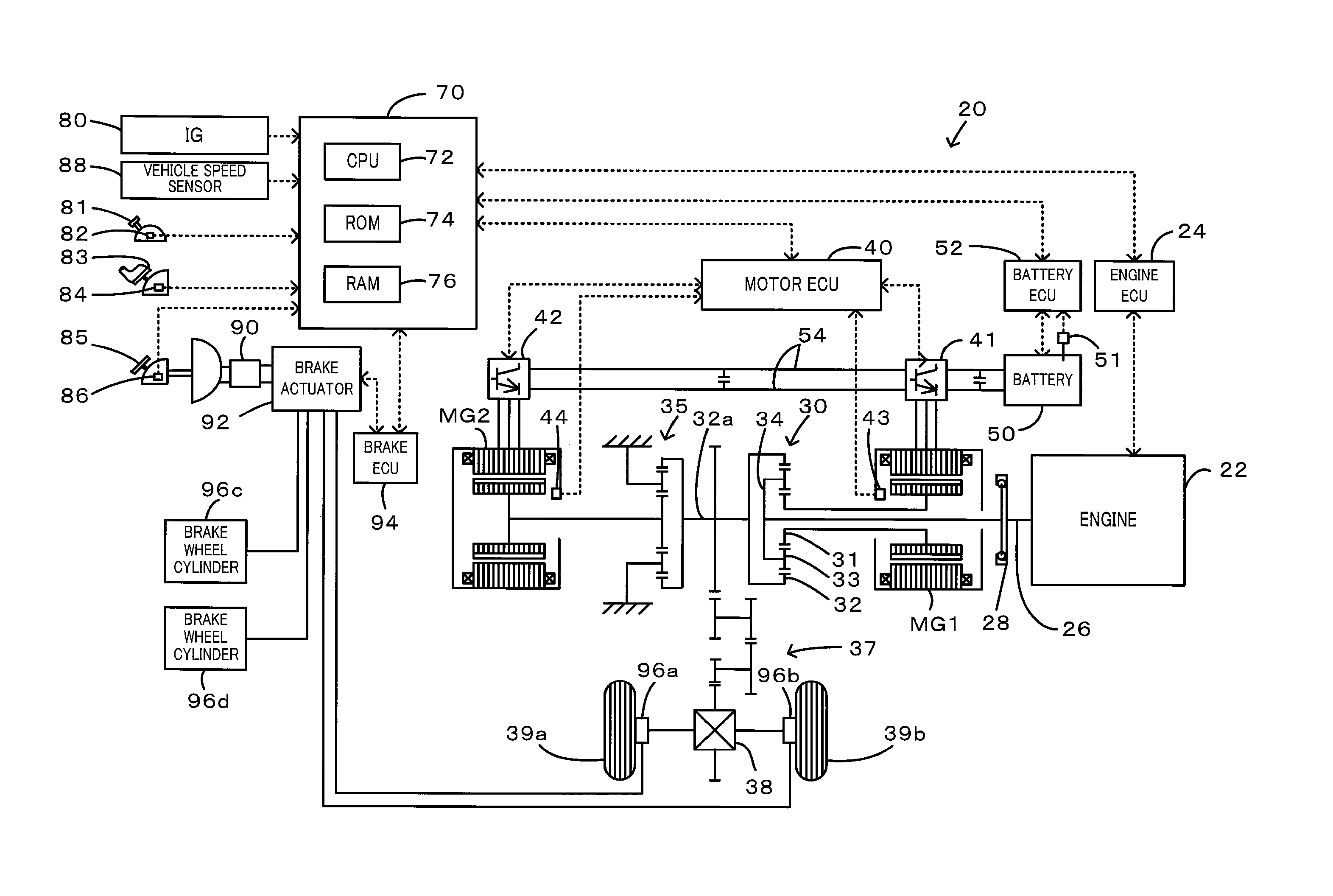
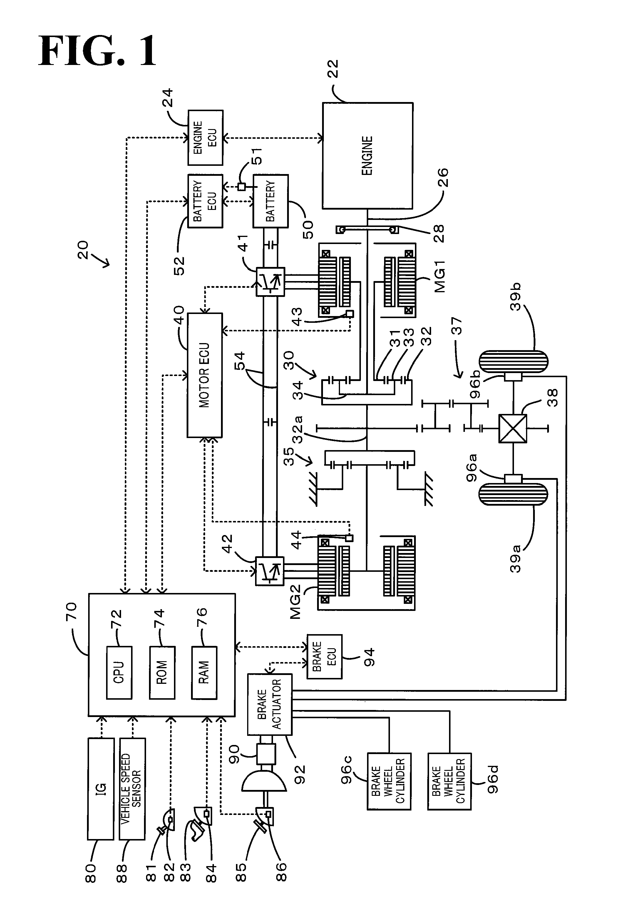
[0033]One mode of carrying out the invention is described below as a preferred embodiment. FIG. 1 schematically illustrates the configuration of a hybrid vehicle 20 in one embodiment of the invention. As illustrated, the hybrid vehicle 20 of the embodiment includes the engine 22, a three shaft-type power distribution integration mechanism 30 connected via a damper 28 to a crankshaft 26 or an output shaft of the engine 22, a motor MG1 connected to the power distribution integration mechanism 30 and designed to have power generation capability, a reduction gear 35 attached to a ring gear shaft 32a or a driveshaft linked with the power distribution integration mechanism 30, a motor MG2 connected to the reduction gear 35, a brake actuator 92 configured to control brakes for drive wheels 39a and 39b and for driven wheels (not shown), and a hybrid electronic control unit 70 configured to control the whole driving system of the hybrid vehicle 20.

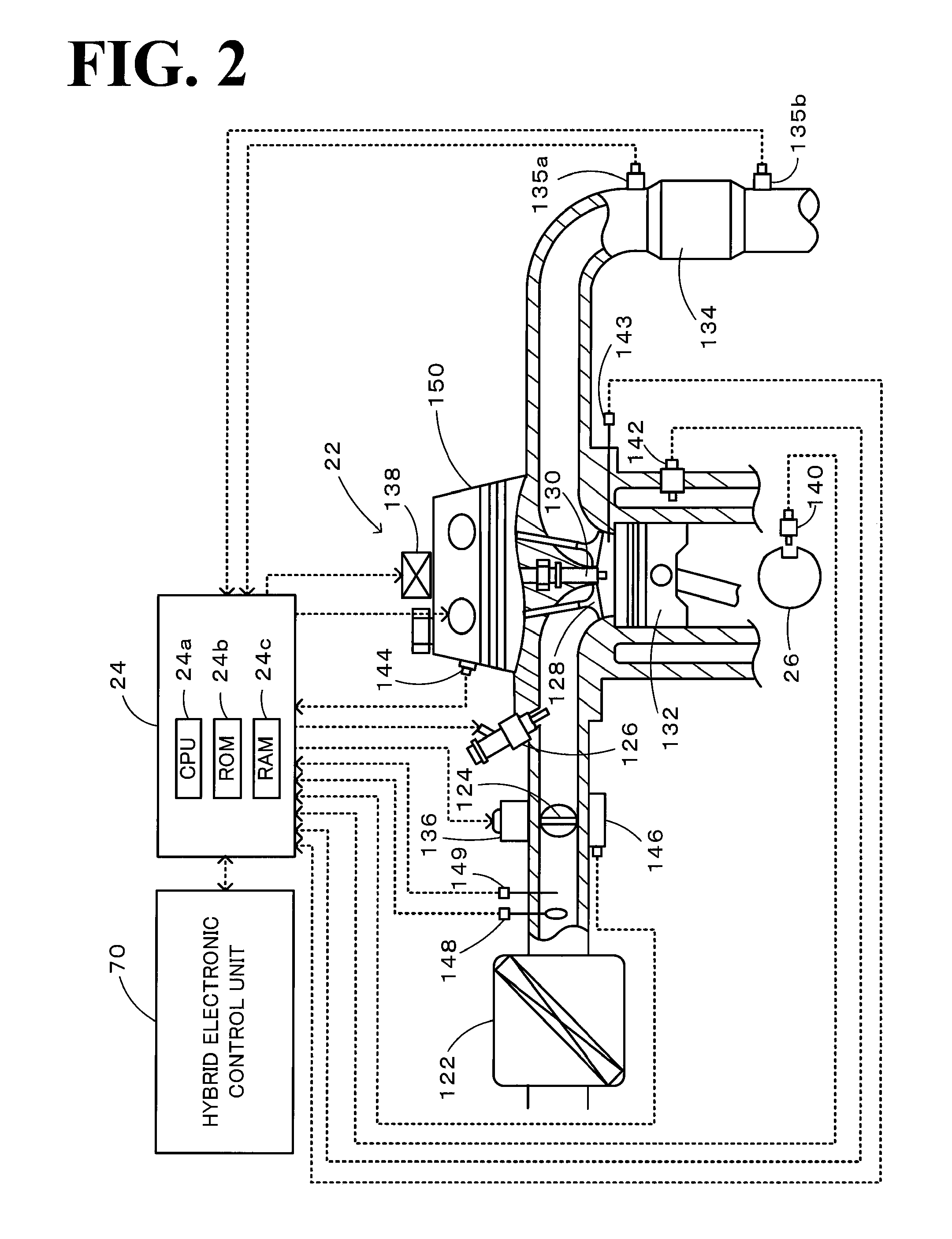
[0034]The engine 22 is an internal combustio...


PUM


Abstract

On the occasion of a cutoff of fuel supply to an engine in an accelerator-off state, the invention expands a throttle opening over a specific throttle opening set in the state of idling of the engine at the reference rotation speed. On resumption of fuel injection to the engine, the invention reduces the throttle opening to the specific throttle opening set in the state of idling of the engine at the reference rotation speed. Under no control of lowering the rotation speed of the engine by a motor or under the condition of low vehicle speed with control of lowering the rotation speed of the engine by the motor, the invention resumes fuel injection to the engine resumed with setting of a smaller correction amount to a fuel increase correction amount.

Description

TECHNICAL FIELD [0001]The present invention relates to a power output apparatus, an internal combustion engine system, and their control methods. More specifically the invention pertains to a power output apparatus constructed to output power to a driveshaft, an internal combustion engine system including an internal combustion engine equipped with a catalytic converter using a catalyst of high oxygen storage capacity to purify the exhaust gas, and control methods of such a power output apparatus and such an internal combustion engine system.BACKGROUND ART [0002]One proposed technique for a vehicle equipped with such a power output apparatus increases the amount of intake air in the state of a cutoff of fuel supply to an engine during deceleration, with a view to reducing the potential smell of a catalyst (see, for example, Patent Document 1). The smell of the catalyst is given by release of hydrogen sulfide converted from sulfur oxides carried on a catalyst, which is used to reduce...

Claims


Application Information

Patent Timeline
IPC IPC(8): F02D41/30B60L50/15B60L50/16
CPCB60K1/02B60L2260/28B60K6/445B60K6/448B60K6/52B60W10/06B60W20/00F01N3/10F01N3/101F02D41/0005F02D41/126F02D2200/501F16H2037/0866Y02T10/6239Y02T10/6243Y02T10/6265Y02T10/42Y02T10/22B60L7/14B60L7/18B60L7/26B60L11/123B60L11/14B60L11/1861B60L15/20B60L15/2009B60L2210/20B60L2210/40B60L2220/14B60L2220/52B60L2240/12B60L2240/36B60L2240/441B60L2240/443B60L2240/445B60L2240/461B60L2240/463B60L2240/545B60L2240/547B60L2240/549B60L2250/24B60L2250/26B60K6/365B60L50/16B60L50/61B60L58/12Y02A50/20Y02T10/12Y02T10/40Y02T10/62Y02T10/64Y02T10/70Y02T10/7072Y02T10/72B60W10/08B60W2530/12
Inventor ANDO, IKUO
Owner TOYOTA JIDOSHA KK
Why Eureka
Try Eureka