Smart charge system for electric vehicles integrated with alternative energy sources and energy storage

Inactive Publication Date: 2010-02-18
GU GONG EN +2
View PDF9 Cites 100 Cited by
  • Summary
  • Abstract
  • Description
  • Claims
  • Application Information

AI Technical Summary

Benefits of technology

[0016]Fourth, the siting of recharging stations will be chosen to coincide with locations where vehicles are usually parked for extended times. Noting that cars are parked for long periods while the drivers are on business, at work, shopping, or dining, the parking structures and parking lots for malls, office buildings, restaurants, theatres, transit terminal points (commuter rail stations, for example), are all likely locations for a smart charging station. The convergence of the charging service function with the (necessary) parking function of some businesses creates a synergistic commercial effect, since people seeking a vehicle charge will likely patronize the business(es) surrounding the charging station, and people patronizing the businesses will seek the most convenient recharge for their vehicle.
[0017]Integrating energy storage and generation into the charging station also provides a synergistic result, in that the charging station can provide charging from some of its storage capacity and avoid overloading the electrical grid, particularly during prime times for electrical power usage. Likewise, alternative energy generators suc

Problems solved by technology

Second, the system stores the collected electricity in a high capacity energy storage system using batteries, or super-cap

Method used


Image

  • Smart charge system for electric vehicles integrated with alternative energy sources and energy storage
  • Smart charge system for electric vehicles integrated with alternative energy sources and energy storage

Examples


Embodiment Construction

[0021]The present invention generally comprises a system for providing charging services to a driving public that includes users of battery powered electrical vehicles, whether fully electric or plug-in hybrid electric.

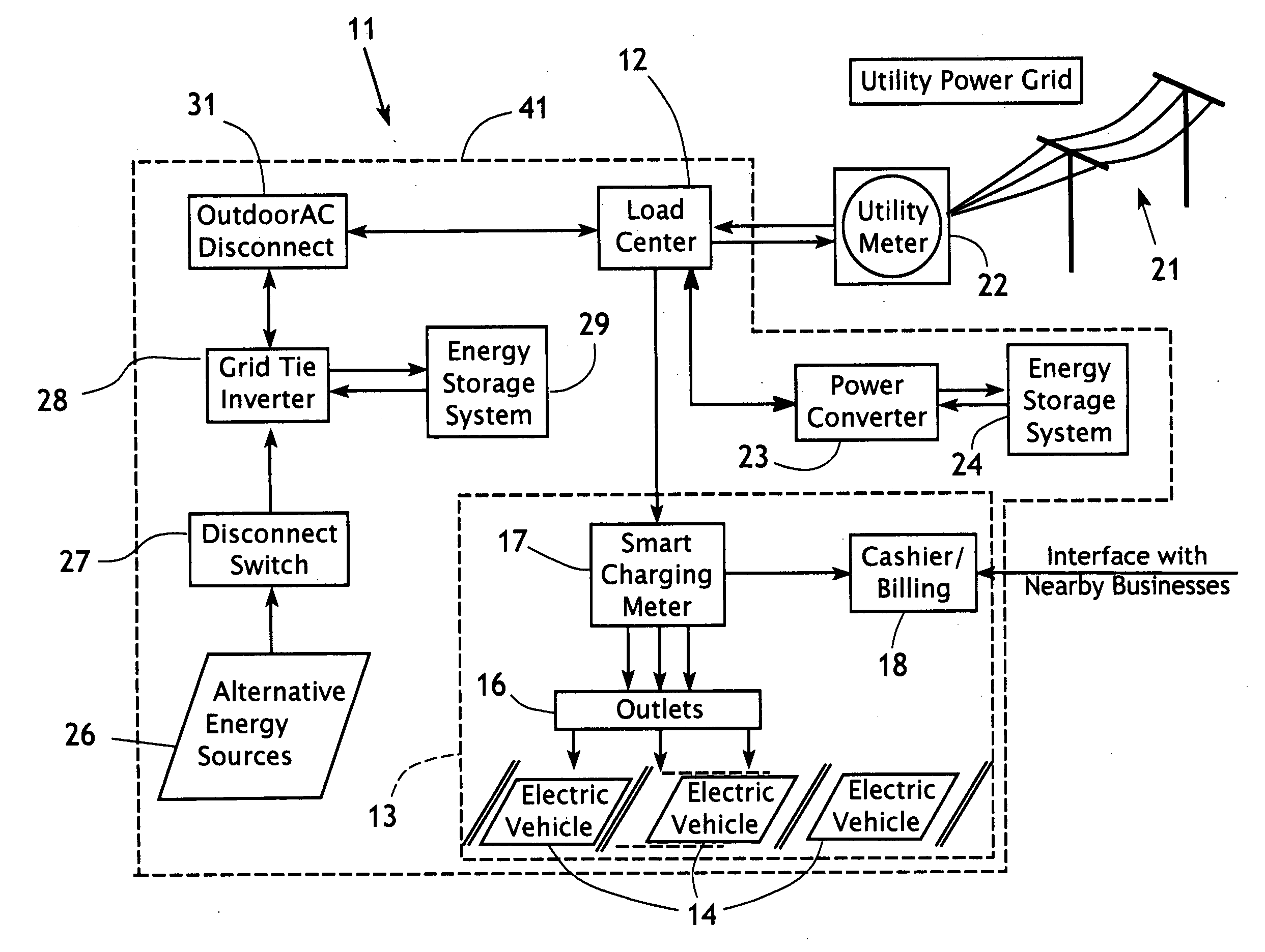
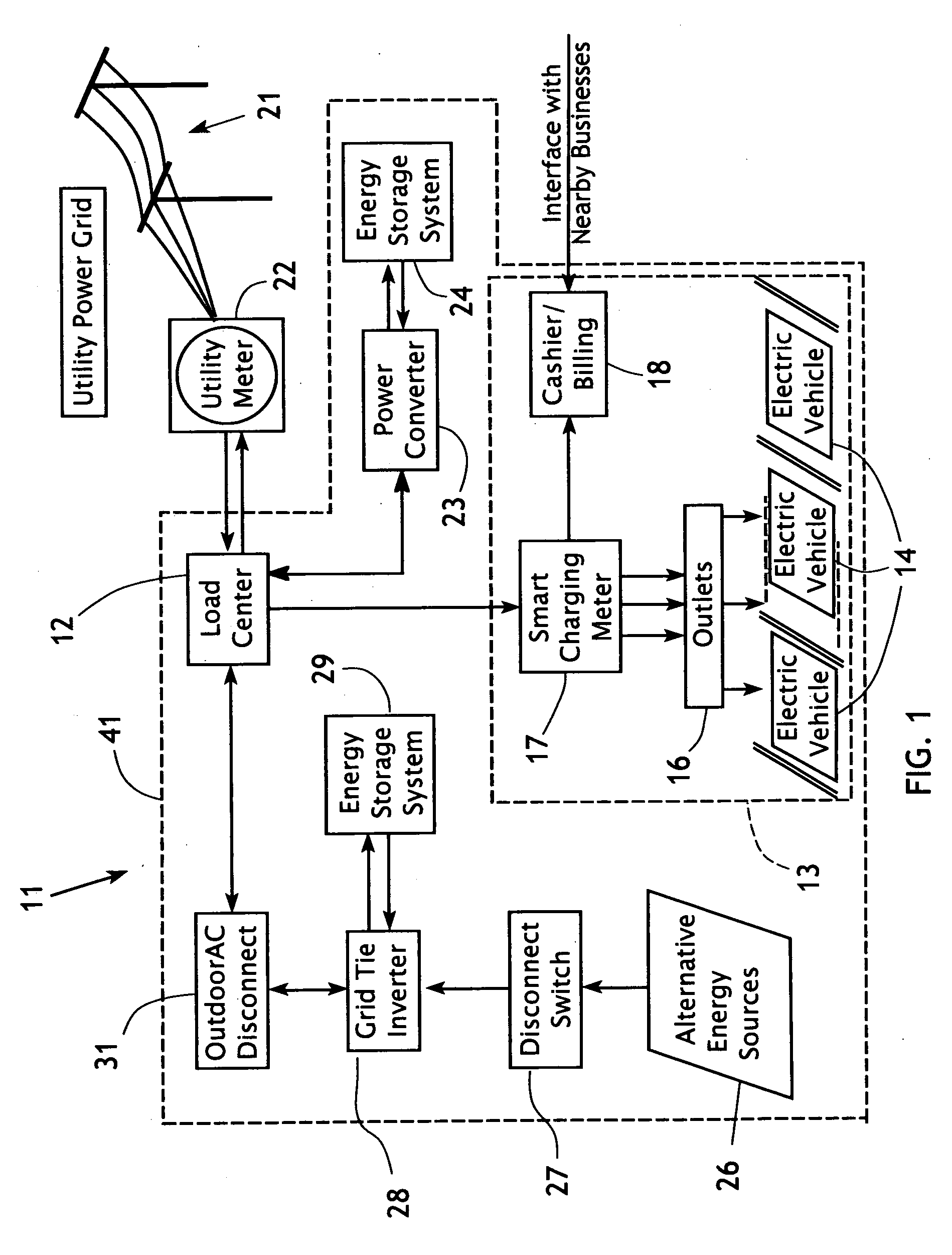
[0022]In general, with regard to FIG. 1 the charging system 11 includes a main electrical load center 12 that aggregates power from a plurality of sources and feeds power to a vehicle charging lot 13, where a plurality of electric vehicles 14 may be connected to charging outlets 16. The outlets 16 are preferably arrayed to serve separate vehicle parking spots within the charging lot 13, and are connected to a smart charging meter 17. The smart charging meter 17 tracks the identification of each vehicle 14 connected to the system, and data such as the amount of power delivered, time of charge, state of charge, and the like, as well as credit / debit / cash data to complete the transaction for payment for the recharging service. The transaction data is fed to a cashier / bill...


PUM


Abstract

A charging system for electrical vehicle batteries has a smart charge power meter with a computer control system to measure and integrate the delivered electrical power, enable/disable the charging stations and make all of the other necessary purchasing transaction steps equivalent to a gas station operation. The system may collect electricity by using whatever alternative energy system is available or can be incorporated into the charging system when it is constructed. The system may store the collected electricity in a high capacity energy storage system. The charging takes place at a charging lot which is within a secure perimeter to assure safety and prevent vandalism. The siting of charging lots is chosen to coincide with locations where vehicles are usually parked for extended times (e.g., parking lots, businesses, etc.).

Description

CROSS-REFERENCE TO RELATED APPLICATIONS[0001]This application claims the priority benefit of the filing date of U.S. Provisional Appl. No. 61 / 189,242, filed Aug. 18, 2008.FEDERALLY SPONSORED RESEARCH[0002]Not applicable.SEQUENCE LISTING, ETC ON CD[0003]Not applicable.BACKGROUND OF THE INVENTION[0004]1. Field of the Invention[0005]This invention relates to the recharging of rechargeable electrical vehicles and other large capacity portable electrical devices, as well as commercial models for providing recharging services to electrical vehicle operators and owners.[0006]2. Description of Related Art[0007]The rising cost of oil, and concerns about global climate change leads to an increasing demand for alternative energy solutions for transportation and other types of energy-consuming industries. For the individual consumer, the biggest problem is costs arising from the gasoline expense for their cars from daily commuting. This financial pressure is increasing as petroleum product pric...

Claims


Application Information

Patent Timeline
IPC IPC(8): H02J7/00G01R21/133
CPCB60L8/003Y02T90/121B60L11/1842B60L11/1846B60L11/1848G06Q50/06G07F15/005Y02E60/721Y02T10/7005Y02T10/7083Y02T10/7094Y02T90/128Y02T90/14Y02T90/163Y02T90/169Y04S10/126Y04S30/14B60L2200/26B60L11/1838Y02T10/7072B60L55/00B60L53/65B60L53/665B60L53/67B60L53/66Y02E60/00Y02T10/70Y02T90/12Y02T90/167Y02T90/16
Inventor GU, GONG-ENSU, CHAOSTERLING, WILLIAM DOUGLAS
Owner GU GONG EN
Why Eureka
Try Eureka