Electrostatic chuck assembly

Active Publication Date: 2010-02-18
APPLIED MATERIALS INC
View PDF16 Cites 320 Cited by
  • Summary
  • Abstract
  • Description
  • Claims
  • Application Information

AI Technical Summary

Benefits of technology

[0014]Embodiments of the present invention provide a cost effective electrostatic chuck which can: operate over wide temperature ranges

Problems solved by technology

However, it is difficult to attach metal components to or embed metal components (e.g., electrodes) within the ceramic chuck body because of differences in the thermal expansion coefficients (CTE) of the ceramic and metal which can result in thermo-mechanical stresses that can cause the ceramic to fracture or chip during thermal cycling.
Additionally, differences in the CTEs may increase with temperature resulting in greater thermo-mechanical stresses at higher t

Method used


Image

  • Electrostatic chuck assembly
  • Electrostatic chuck assembly
  • Electrostatic chuck assembly

Examples


Embodiment Construction

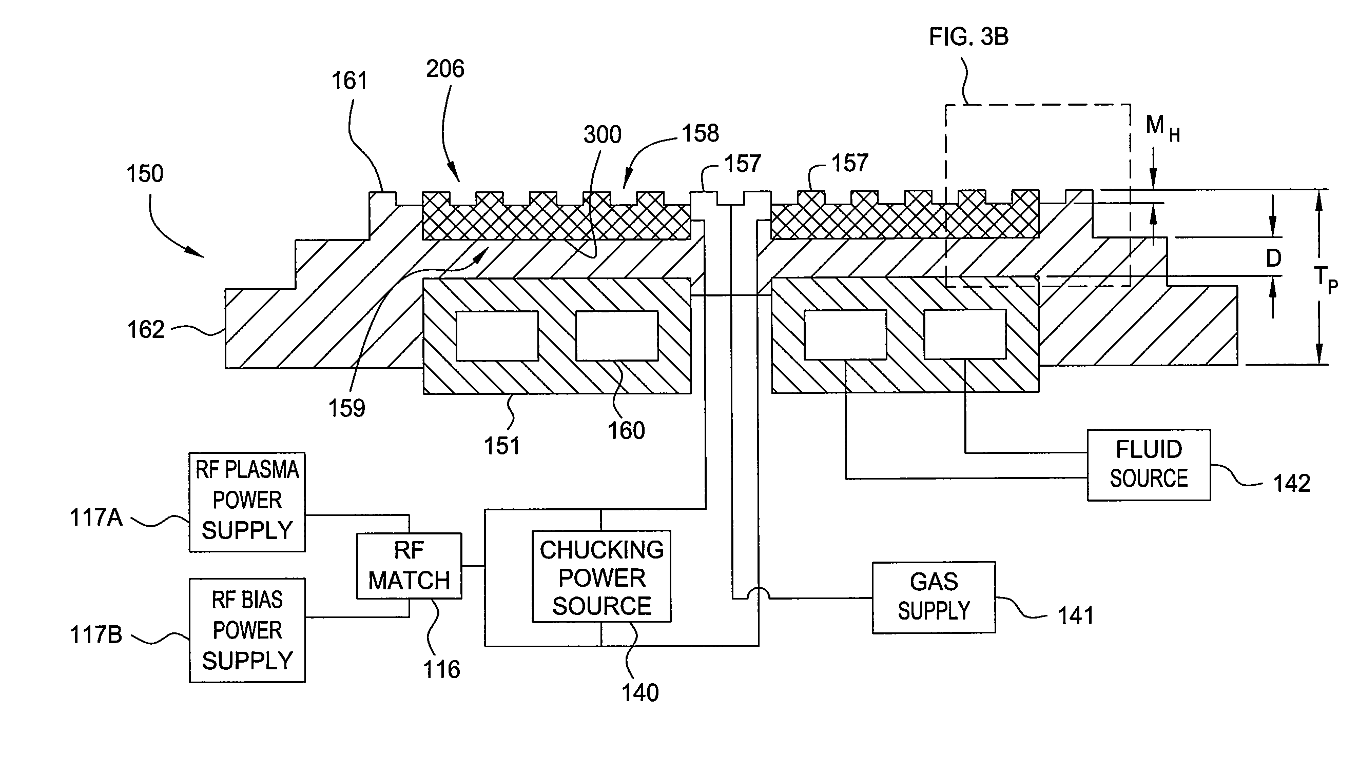
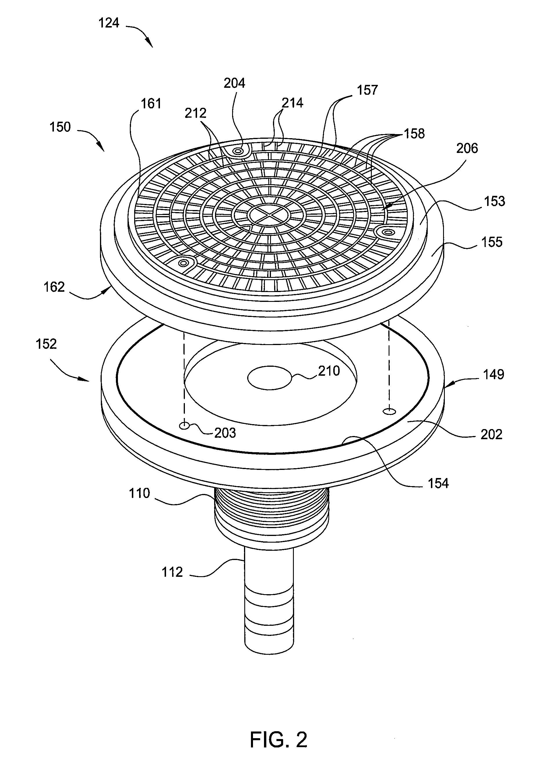
[0033]The present invention generally provides a robust, cost effective electrostatic chuck capable of operating over wide temperature ranges in ultra-high vacuum environments. Embodiments of the invention include an electrostatic chuck assembly which provides efficient radio frequency coupling for substrate biasing and / or plasma formation.

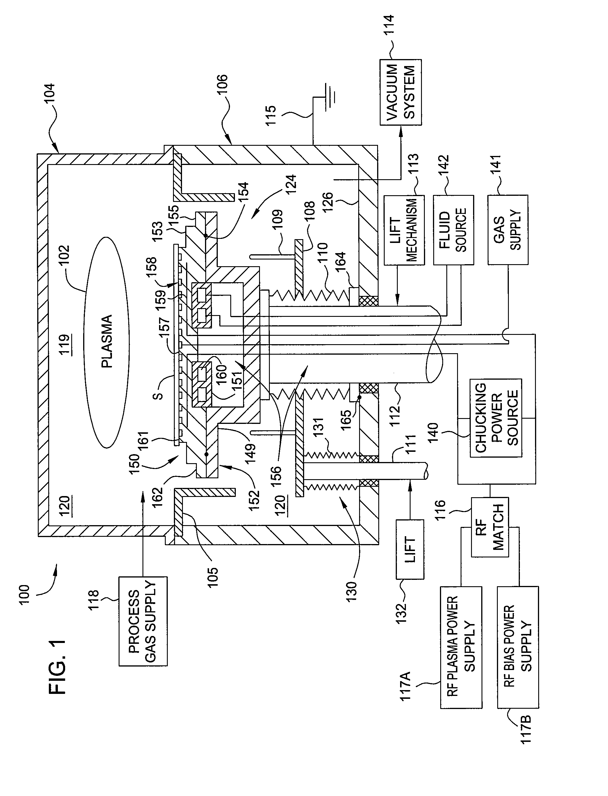
[0034]FIG. 1 is a schematic cross-sectional view of plasma processing chamber according to one embodiment of the invention. In one embodiment, the plasma processing chamber is a sputter etch processing chamber. However, other types of processing chambers, such as physical vapor deposition (i.e., sputtering) chambers, for example, may also be used to practice the invention.

[0035]A chamber 100 is a vacuum chamber which is suitably adapted to maintain sub-atmospheric pressures within a chamber interior volume 120 during substrate processing. The chamber 100 includes a chamber body 106 covered by a dome 104 which encloses a processing volume 119 locat...


PUM


Abstract

Embodiments of the present invention provide a cost effective electrostatic chuck assembly capable of operating over a wide temperature range in an ultra-high vacuum environment while minimizing thermo-mechanical stresses within the electrostatic chuck assembly. In one embodiment, the electrostatic chuck assembly includes a dielectric body having chucking electrodes which comprise a metal matrix composite material with a coefficient of thermal expansion (CTE) that is matched to the CTE of the dielectric body.

Description

CROSS-REFERENCE TO RELATED APPLICATIONS[0001]This application claims benefit of provisional U.S. Patent Application Ser. No. 61 / 088,289, filed Aug. 12, 2008, entitled “Electrostatic Chuck Assembly,” and is hereby incorporated by reference in its entirety.BACKGROUND OF THE INVENTION[0002]1. Field of the Invention[0003]Embodiments of the present invention generally relate to substrate supports used in processing chambers for fabricating microelectronic devices and, more specifically, to electrostatic chucks used in plasma processing chambers.[0004]2. Description of the Related Art[0005]Electrostatic chucks are widely used to hold substrates, such as semiconductor wafers, during substrate processing in processing chambers used for various applications, such as physical vapor deposition, etching, or chemical vapor deposition. Electrostatic chucks typically include one or more electrodes embedded within a unitary chuck body which comprises a dielectric or semi-conductive ceramic material...

Claims


Application Information

Patent Timeline
IPC IPC(8): H01L21/683
CPCH01L21/6833H01L21/68785H02N13/00H01J37/32431H01L21/67103H01L2924/0002H01L21/67109H01L21/6831H01L2924/00B23Q3/15H01L21/68H01L21/687
Inventor SANSONI, STEVEN V.TSAI, CHENG-HSIUNGROY, SHAMBHU N.BROWN, KARL M.PARKHE, VIJAY D.PONNEKANTI, HARI
Owner APPLIED MATERIALS INC
Why Eureka
Try Eureka