Composite Armor and Method for Making Composite Armor

Active Publication Date: 2010-02-25
BATTELLE MEMORIAL INST
View PDF36 Cites 49 Cited by
  • Summary
  • Abstract
  • Description
  • Claims
  • Application Information

AI Technical Summary

Benefits of technology

[0011]The use of the strike face of the present invention attached to a back plate forms a composite armor panel that has single hit performance, multi-hit performance, is light weight, and inexpensive to manufacture. The multi-

Problems solved by technology

However they have the disadvantage of being very heavy.
The challenge to developing multi-hit ceramic armor is to control the damage created in the ceramic plates and the backing plate by the impact.
Early in the impact event, this damage can be created by stress wave propagation from the impact site.
This later response of the panel to the threat impulse ca

Method used


Image

  • Composite Armor and Method for Making Composite Armor
  • Composite Armor and Method for Making Composite Armor
  • Composite Armor and Method for Making Composite Armor

Examples


example 1

Manufacturing Composite Armor Panel

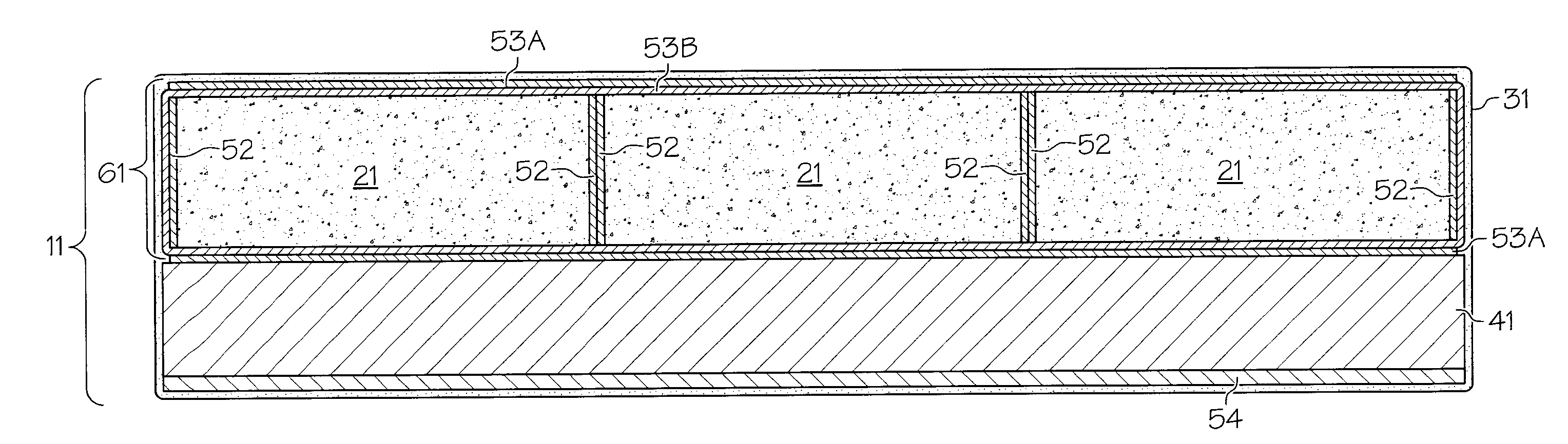
[0053]Process for cleaning ceramic tiles (21):[0054]1) The ceramic tiles (21) were cleaned along all six surfaces via a mechanical blasting process using Aluminum Oxide media across the entirety of the surfaces.[0055]2) The ceramic tiles (21) were further cleaned in a solvent to remove residual dust, oils, and other contaminants not removed completely by the blasting process.

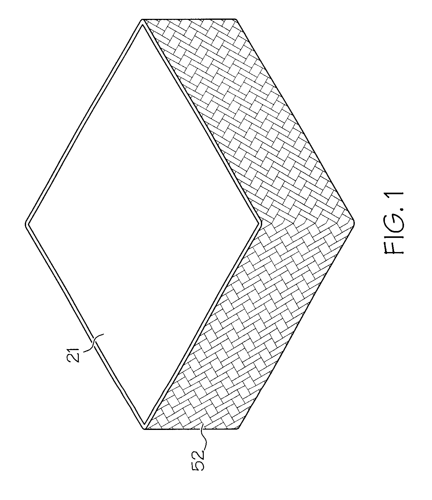
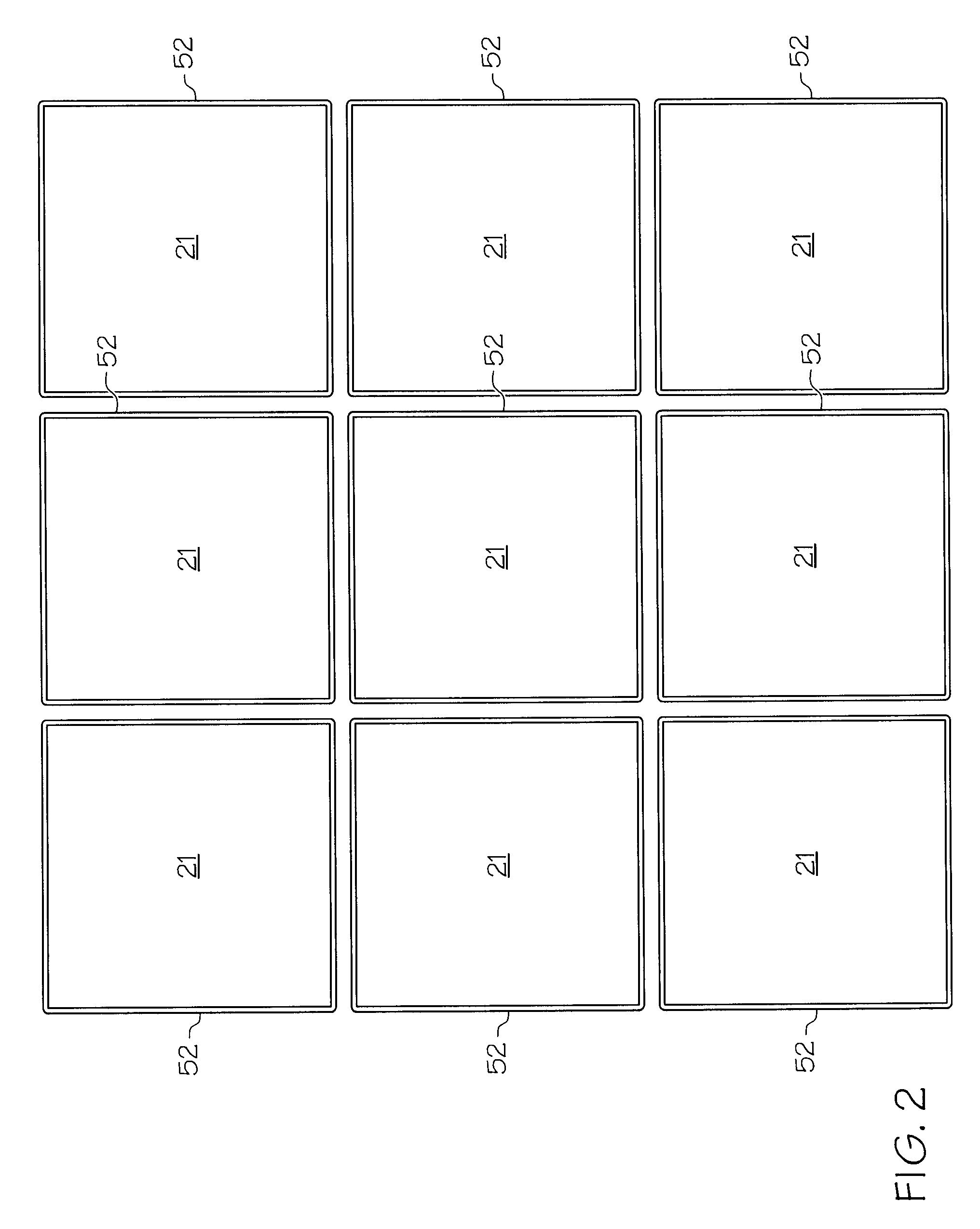
[0056]Process for edge wrapping ceramic tiles (21):[0057]1) The ceramic tiles (21) were loaded onto a winding mandrel and the liquid crystal polyester-polyarylate fiber was wrapped around the 8 mm-thickness edge of the ceramic tiles (21).[0058]2) The liquid crystal polyester-polyarylate fiber was wound in the following manner: Three rows of three liquid crystal polyester-polyarylate HT1500 / 300 / T150 yarn, epoxied at corners (61.26% Epon Resin 828, 26.24% Epodil 757 and 12.50% Epi-Cure 3200), gapped (three tows per edge) single edge wrapped.[0059]3) The epoxy was allowed to cure ...

example 2

Comparison Armor Panel

[0085]A composite armor panel was made according to procedure in Example 1, except the hyperelastic polymer (31) was substituted with a non-hyperelastic polymer shown below.

[0086]A polymer resin was formed from an MDI-terminated prepolymer with a polypropylene glycol backbone (Baytec MP-210), 1,4-butanediol (a short-chain curative), an ethylene-glycol capped polypropylene glycol triol with a molecular weight of approximately 6000 (Mutranol 3901), and a catalyst system containing a 4:1 blend of a tertiary amine catalyst and a tin-based catalyst. The ingredients were degassed, mixed at room temperature, and poured into a hot mold to make a composite armor panel. The panel was allowed to cure in the mold at a temperature of about 93° C. to 110° C. for a minimum of 30 minutes before being removed from the mold and post-cured.

example 3

Ballistic Test

[0087]Testing of Example 1 and 2 armor panels was performed to NIJ Level IV standards with a 7.62 mm AP M2 at ˜2,850 fps. After the test the panels were examined and it was found that the back plate delaminated from the strike face of the Example 2 armor panel, while the back plate did not delaminate from the strike face of the Example 1 armor panel.


PUM

PropertyMeasurementUnit
Fractionaaaaaaaaaa
Fractionaaaaaaaaaa
Percent by massaaaaaaaaaa

Abstract

A composite armor panel and a method for making the armor is disclosed. In one embodiment the armor consists of a plurality of ceramic tiles (21) individually edge-wrapped (52) with fiber or edge-wrap fabric, which are further wrapped with a face-wrap fabric, and encapsulated in a hyperelastic polymer material (31) permeating the fabric and fibers, with a back plate (41) adhered to the encapsulated tiles. In one embodiment the hyperelastic polymer (31) is formed from a MDI-polyester or polyether prepolymer, at lease one long-chain polyester polyol comprising ethylene/butylene adipate diol, at least one short-chain diol comprising 1,4-butanediol, and a tin-based catalyst.

Description

CROSS REFERENCE TO RELATED APPLICATIONS[0001]The present application hereby claims the benefit of the provisional patent application of the same title, Ser. No. 60 / 868,371, filed on Dec. 4, 2006, the disclosure of which is hereby incorporated by reference in its entirety.BACKGROUND OF THE INVENTION[0002]The present invention relates, in general, to a composite armor and a process for forming a composite armor.[0003]Composite armor containing ceramics and high strength fibers have been useful to provide protection against ballistic projectiles. Typical existing armor for vehicles use rigid plates of steel. However they have the disadvantage of being very heavy. Ceramic containing armor systems have demonstrated great promise as reduced weight armors. These armor systems function efficiently by shattering the hard core of a projectile during impact on the ceramic material. The lower velocity bullet and ceramic fragments produce an impact, over a large “footprint”, on a backing plate w...

Claims


Application Information

Patent Timeline
IPC IPC(8): F41H5/04F41H5/06B32B37/24
CPCF41H5/0421F41H5/0435B32B9/005B32B9/045B32B27/34B32B2607/00B32B27/40B32B2307/51B32B2307/536B32B2571/00B32B27/36
Inventor SAYRE, JAYVERSLUIS, SCOTTVALENTINE, KARY L.
Owner BATTELLE MEMORIAL INST
Why Eureka
Try Eureka