Injection molding process, resin molded product and mold

a technology of injection molding and resin molded products, which is applied in the direction of identification means, instruments, applications, etc., can solve the problems of increasing the cost of parts, taking labor costs, and affecting the appearance quality of the product, and achieves high production efficiency and high appearance quality

Inactive Publication Date: 2010-02-25
CANON KK
View PDF0 Cites 6 Cited by
  • Summary
  • Abstract
  • Description
  • Claims
  • Application Information

AI Technical Summary

Benefits of technology

[0008]According to the present invention, the compression shape portion having a larger wall thickness than the gate portion is provided, so that the resin at the gate is cooled and solidified upon cutting of the gate not to cause backward flow of the resin toward the runner, and besides the appearance of the resulting part is not deteriorated by cutting because no cut surface is present at the product shape portion. Since a cut portion can be made into a shape continuing from the product shape portion, productivity is high in the production of a wide variety of resin molded products, and molded products high in appearance quality can be obtained.

Problems solved by technology

Since these sprue, runner and gate portions have no product function and are unnecessary portions, these portions are discarded or reused by remelting or the like after being cut off from the product shape portion after molding.
However, it takes a labor cost since a worker cuts off the gate portion using a cutting tool such as nippers after the sprue and runner portions are taken out of the mold.
In addition, an automatic machine for cutting has involved a cost problem such as increase in part cost due to the cost of the automatic machine.
In the pin-gate method, however, the mold is in the form called a three-plate mold, so that the pin-gate method has involved such problems as complication of the mold structure, increase in molding cycle and material cost due to increase in runner volume, and increase in mold thickness.
Further, a direct gate type in which a gate of a hot runner is directly provided on a product has the merit not only that no scrap material is produced but also that cutting of the gate is unnecessary.
However, it is often difficult from the viewpoints of product function and design to directly provide the gate on the product shape portion, and moreover there arise such problems not only that increase in mold cost is brought because the hot runner itself is expensive but also that maintenance is hard because the mold structure is complicated.
In these conventional molds and methods, it is very difficult, for the method in which the slope surface is provided on the gate cutting pin and thus the gate cutting pin causes the resin in the gate portion to flow backward to the side of the runner, to return the resin to the side of the runner by the slope surface of the gate cutting pin before or just after completion of the pressure holding.
However, the enlargement of the runner size has involved problems that a molding cycle is elongated because the runner cooling time is long and that a scrap material is increased by an amount corresponding to the enlargement.
However, it is necessary to conduct the cutting of the gate by the gate cutting pin before the gate is solidified, so that there arises such a problem of trade-off between the pressure holding and the timing of the gate cutting that a sufficient pressure cannot be applied to the product shape portion.
In addition, when the thickness of the gate is made greater than the product shape portion, a problem that flash is produced on a gate-cutting surface on the side of the product has arisen in addition to the problems that the molding cycle is elongated and the scrap material is increased, like the case where the runner is enlarged.
Thus they involve such defects that it is difficult to retain the product surface quality at the gate equivalent to that of the product surface around the gate.

Method used


Image

  • Injection molding process, resin molded product and mold
  • Injection molding process, resin molded product and mold
  • Injection molding process, resin molded product and mold

Examples


Embodiment Construction

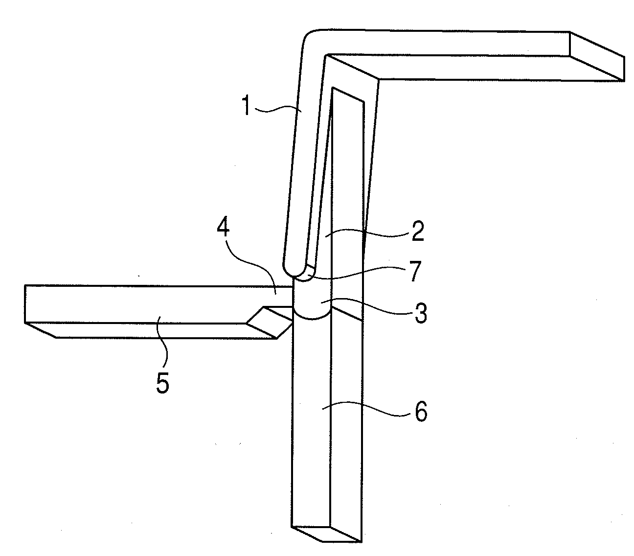
[0033]The construction and operation of a resin molding mold according to the present invention will be described with reference to the drawings.

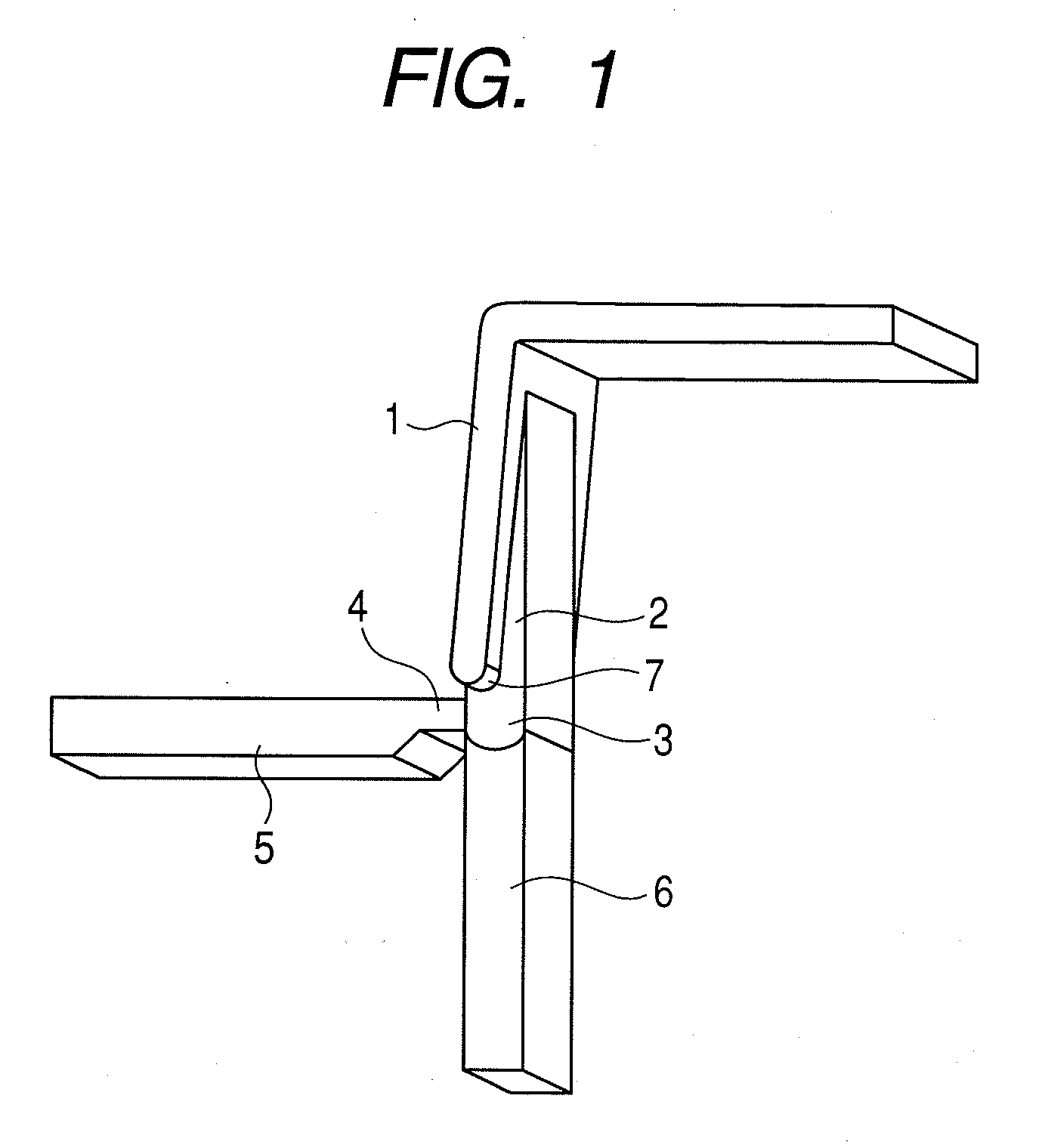
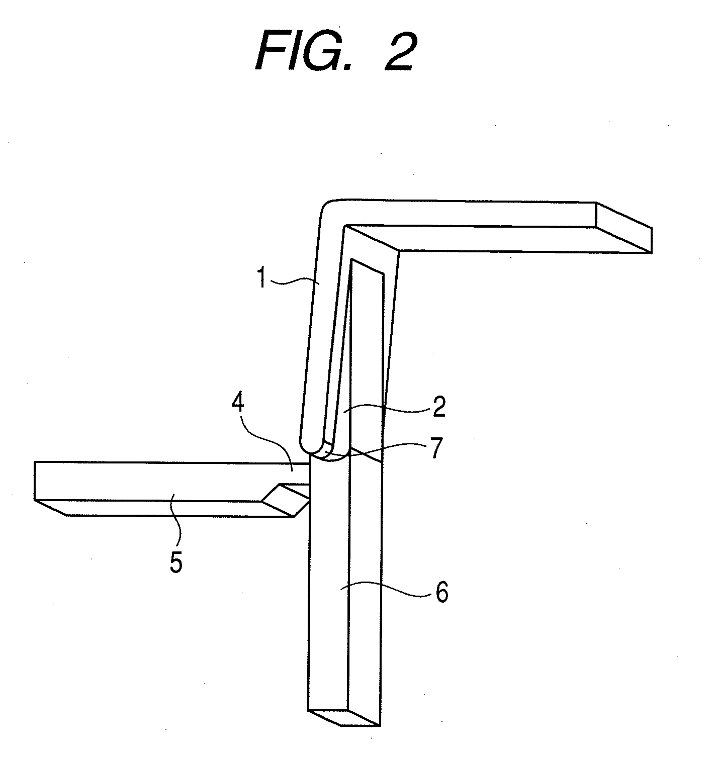
[0034]FIG. 1 illustrates an exemplary embodiment showing the fundamental constitution of the present invention and is a schematic view in the vicinity of a gate just after a resin is filled into a mold. In FIG. 1, are illustrated a part shape portion 1, a compression-purpose thick portion 2 which is opposed to a cutting pin 6 and has a large wall thickness than the surrounding part shape portion 1, a compression shape portion 3, a gate portion 4 having a gate at the end thereof, a runner portion 5, a pin- or block-shaped cutting pin 6, and a product end surface 7. The parts shape portion 1 and the compression-purpose thick portion 2 constructs a product shape portion, which has a shape to become a product. FIG. 2 illustrates a state just after the gate has been cut off in the present invention.

[0035]Operation will now be described with refe...


PUM

PropertyMeasurementUnit
thicknessaaaaaaaaaa
thicknessaaaaaaaaaa
thicknessaaaaaaaaaa

Abstract

The invention provides an injection molding process, in which a gate is cut off within a mold in resin molding to obtain a good gate-cut surface, as well as a resin molded product and a resin molding mold. In the injection molding process, a cutting pin, which is connected to a cutting pin working plate provided in parallel with a driving device or an ejector plate provided in a mold, slides on a mold parting line between a fixed-side block, on which corner cutting or a R shape is provided at the approach port, and a movable-side block opposed to the fixed-side block. The wall thickness of a compression shape portion opposed to the cutting pin is larger than that of a gate and a product shape portion. The cutting pin compresses a resin in this portion toward the product shape portion at predetermined timing to cut off the gate portion and integrate the resin with the product shape.

Description

TECHNICAL FIELD[0001]The present invention relates to an injection molding process in which a resin material is melted, injected into a mold worked into a desired shape, cooled and solidified, and a molded product is then taken out of the mold, as well as a resin molded product and a mold.BACKGROUND ART[0002]A process in which a molten resin material is injected into a mold worked into a desired shape in advance and cooled and solidified in the mold, and the mold is then opened to take a molded product out of the mold, has been widely known as an injection molding process and utilized. A product shape portion for a molded product having a product function and an ingate (nozzle portion) of a molding machine for injecting a molten resin into a mold are generally connected through such portions as to be called a sprue, a runner and a gate. FIG. 23 illustrates a side-gate mold generally used. The mold includes an injection port 48 of a nozzle part, a gate 51, a runner 52, a sprue 53, a ...

Claims


Application Information

Patent Timeline
Patent Type & Authority Applications(United States)
IPC IPC(8): B29C45/40B32B17/10
CPCB29C45/38Y10T428/15B29C45/561
Inventor ARAI, TAKASHI
Owner CANON KK
Why Eureka
Try Eureka