Separation technology method and identification of error

a separation technology and error detection technology, applied in the field of separation technology methods and errors, can solve the problems of insufficiently addressed limitations and problems in separation technology, components in overlapped peaks often cannot be distinguished, and limitations of separation technology

Inactive Publication Date: 2010-03-04
WOLTERS ANDREW MARK
View PDF9 Cites 49 Cited by
  • Summary
  • Abstract
  • Description
  • Claims
  • Application Information

AI Technical Summary

Benefits of technology

[0027]c) measuring at least one of the one or...

Problems solved by technology

These separation techniques are not without their problems and limitations, however.
One of the primary limitations of separation technology is the co-elution of different sample components, wherein the components in the overlapped peaks often cannot be distinguished.
In addition to the problem of co-elution of different sample components, other limitations and problems such as analysis run time and sensitivity have also received substantial attention in research and development to improve performance.
However, there are other limitations and problems in separation technology that have not been adequately addressed.
In separation technology, one critical problem is where the desired sample component might not reach (or only partially reach) the detector after being subjected to the separation technique during the method run time.
If the sample component does not reach the detector after the sample is subjected to separation, the sample component will not be identified and the interpretation of the experiment can be invalid, perhaps critically.
A situation might exist where a cross-contaminant in a pharmaceutical drug might not be detected wherein the contaminant could be detrimental or even fatal to the patient taking the drug with the unknown contaminant.
Unfortunately, this type of problem can arise across all different types of separation techniques.
Sometimes a peak retained during one run will elute during a subsequent run, leading to a contaminant peak.
Moreover, sometimes one or more sample components will be retained by the stationary phase so strongly that they cannot be eluted with any of the different mobile phases used in the particular separation technique.
In practice, sometimes anionic components do not reach the detector since their electrical repulsion is too strong for the electro-osmotic flow to overcome.
Another critical problem in separation technology is sample component degradation during separation.
In electrophoresis, the applied voltage causes Joule heating, which can lead to sample component degradation.
Other factors can cause sample degradation.
While degradation during separation can occur for small mole...

Method used


Image

  • Separation technology method and identification of error
  • Separation technology method and identification of error
  • Separation technology method and identification of error

Examples


example 1

HPLC-UV / Vis of Samples

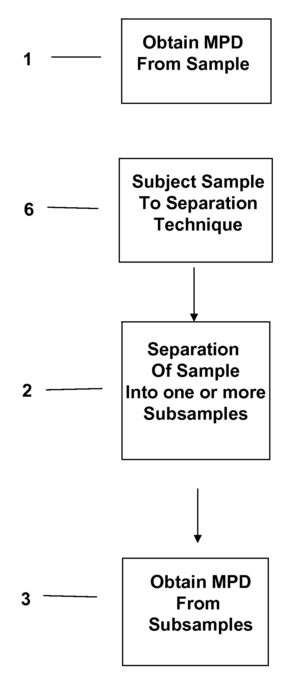
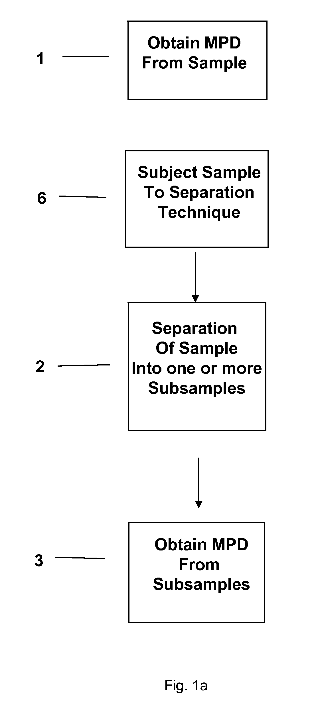
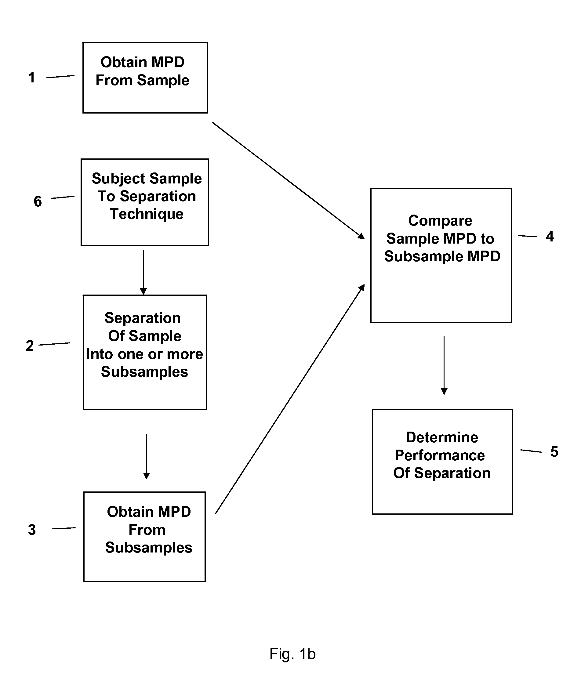
[0166]A HPLC instrument with UV / Vis diode-array detection uses the following method to analyze samples: obtain a UV / Vis spectrum from the sample prior to chromatographic separation, subject the sample to a chromatographic separation, obtain a series of on-line continuous-flow UV / Vis spectra from the subsamples after the chromatographic separation, compare the combined UV / Vis spectra from the subsamples measured after chromatographic separation to the UV / Vis spectrum of the sample obtained before chromatographic separation. In this particular example, the HPLC instrument collects both the pre-separation and post-separation UV / Vis spectra from one flow cell by switching flow paths (see FIG. 3). In this particular example, the HPLC instrument uses a liquid-core waveguide as the flow cell for UV / Vis measurements to minimize effects of index of refraction on optical pathlength. In this particular example, the flow cell temperature is set to 25 C during the analysis....

example 2

HPLC-UV / Vis-MS of Samples

[0175]A HPLC instrument with UV / Vis diode-array detection and MS detection uses the following method to analyze samples: inject a first aliquot volume of the sample for analysis, obtain an on-line continuous-flow UV / Vis spectrum from the sample prior to any type of separation, conduct a scout separation on a short chromatographic column, obtain a series of on-line continuous-flow MS spectra from the sample (which has potentially been separated) after being subjected to the scout separation, inject a second aliquot volume of the sample for analysis, subject the sample to a comprehensive chromatographic separation, obtain a series of on-line continuous-flow UV / Vis spectra and MS spectra from the subsamples after the comprehensive separation, compare the composite UV / Vis spectra from the subsamples measured after chromatographic separation to the UV / Vis spectrum of the sample obtained before any type of chromatographic separation, compare the list of the peaks ...

example 3

HPLC-UV / Vis of Manufactured Active Pharmaceutical Ingredient to Check Purity

[0191]A HPLC instrument with UV / Vis diode-array detection uses the following method to analyze sample [manufactured Active Pharmaceutical Ingredient (API)] as a quality check to determine purity: obtain a UV / Vis spectrum from the sample prior to chromatographic separation, subject the sample to a chromatographic separation, obtain a series of on-line continuous-flow UV / Vis spectra from the subsamples after the chromatographic separation, subtract the UV / Vis spectra of the subsamples measured after chromatographic separation from the UV / Vis spectrum of the sample obtained before chromatographic separation.

[0192]In this particular example, the API has an unknown impurity present. Following the analysis method, the device first collects a UV / Vis spectrum of the sample prior to separation. Comparing the collected UV / Vis spectrum of the sample to the electronic library UV / Vis reference spectrum, a difference is n...


PUM

PropertyMeasurementUnit
Timeaaaaaaaaaa
Stabilityaaaaaaaaaa
Spectrumaaaaaaaaaa

Abstract

The present invention relates to a method and accompanying device for separating a known or unknown sample into one or more subsamples. By comparing the subsample's measurement profile data to the sample measurement profile data, the performance of the separation can be determined. The separation could be chromatography [such as high-performance liquid chromatography (HPLC), gas chromatography (GC), or the like], electrophoresis [such as capillary electrophoresis (CE) or the like], or another separation technique. The measurement profile data could be ultraviolet/visible (UV/Vis) spectra, mass spectra (MS), or another measurement technique.

Description

[0001]This application claims priority of U.S. provisional application No. 61 / 093,444 filed on Sep. 1, 2008 and is incorporated herein in its entirety by reference.COPYRIGHT NOTICE[0002]A portion of the disclosure of this patent contains material that is subject to copyright protection. The copyright owner has no objection to the reproduction by anyone of the patent document or the patent disclosure as it appears in the Patent and Trademark Office patent files or records, but otherwise reserves all copyright rights whatsoever.BACKGROUND OF THE INVENTION[0003]1. Field of the Invention[0004]The present invention relates to a method for separating a sample into one or more components. In particular the present invention relates to the separating of one or more components of a mixture in a manner to identify potential errors in separation of the one or more components.[0005]2. Description of Related Art[0006]For over a century, separation technology has proved indispensable for providin...

Claims


Application Information

Patent Timeline
IPC IPC(8): G01N37/00G01N1/28G01N30/00B01D57/02H01J49/26G01J3/00G01N21/47G01N21/76G06F15/00G01R33/48
CPCG01N30/8665
Inventor WOLTERS, ANDREW MARK
Owner WOLTERS ANDREW MARK
Why Eureka
Try Eureka