Film deposition apparatus and substrate processing apparatus

a technology of substrate processing and deposition apparatus, which is applied in the direction of chemical vapor deposition coating, coating, metallic material coating process, etc., can solve the problems of contamination of wafers, inability to properly carry out ald (or mld) deposition in this process chamber, and long process tim

Active Publication Date: 2010-03-04
TOKYO ELECTRON LTD
View PDF10 Cites 352 Cited by
  • Summary
  • Abstract
  • Description
  • Claims
  • Application Information

AI Technical Summary

Benefits of technology

[0031]It is a general object of the present invention to provide a novel and useful film deposition apparatus and substrate processing apparatus, in which the above-mentioned problem is eliminated.

Problems solved by technology

When such a deposition chamber is used, it takes a long time for a purge gas to purge the reaction gases, resulting in an extremely long process time because the number of cycles may reach several hundred.
However, in the apparatus disclosed in Patent Document 1, because the reaction gases and the separation gas are supplied downward and then evacuated upward from the evacuation ports provided at the upper portion of the chamber, particles in the chamber may be blown upward by the upward flow of the gases and fall on the wafers, leading to contamination of the wafers.
In the technique disclosed in Patent Document 2, the gas curtain cannot completely prevent mixture of the reaction gases but may allow one of the reaction gases to flow through the gas curtain to be mixed with the other reaction gas partly because the gases flow along the rotation direction due to the rotation of the wafer support member.
Therefore, ALD (or MLD) mode deposition cannot be carried out in a proper manner by this process chamber.
The disclosure of Patent Document 4 does not provide any realistic measures to prevent two source gases (AsH3, TMG) from being mixed.
Moreover, because the evacuation ports are located between the adjacent two gas supplying plates to evacuate the gases upward, particles are blown upward from the susceptor surface, which leads to wafer contamination.
Therefore, it is difficult to perform an MLD (or ALD) mode film deposition.
As a result, a reaction product is generated in the purge gas compartment, which may cause particles to fall onto the wafer.
Thus, if a method of driving the turntable by a stepping motor via a belt drive, which is a turntable driving method usually used in a film deposition apparatus in which a film deposition is carried out in a vacuum chamber, the turntable slips relative to the motor during acceleration and deceleration, which results in an angular displacement of an actual rotational angle with respect to a rotational angle instructed to the motor.
Although a motor for driving the turntable and a power transmission method are not disclosed in Patent Documents 1 through 5, in a method of driving a turntable by a stepping motor via a belt drive, which method is generally used in a film deposition apparatus using a vacuum chamber, because the inertia of the turntable is large, a slip (displacement) in rotational angles is generated between the turntable and a motor shaft due to a slip or a stretch of the belt at a time of start or at a time stop, which results in a loss of synchronism.
As a result, when carrying a substrate into or out of a vacuum pump, there may occur a problem in that the substrate cannot be placed on the turntable with good positional accuracy or the substrate cannot be taken out of the turntable surely.

Method used


Image

  • Film deposition apparatus and substrate processing apparatus
  • Film deposition apparatus and substrate processing apparatus
  • Film deposition apparatus and substrate processing apparatus

Examples


Embodiment Construction

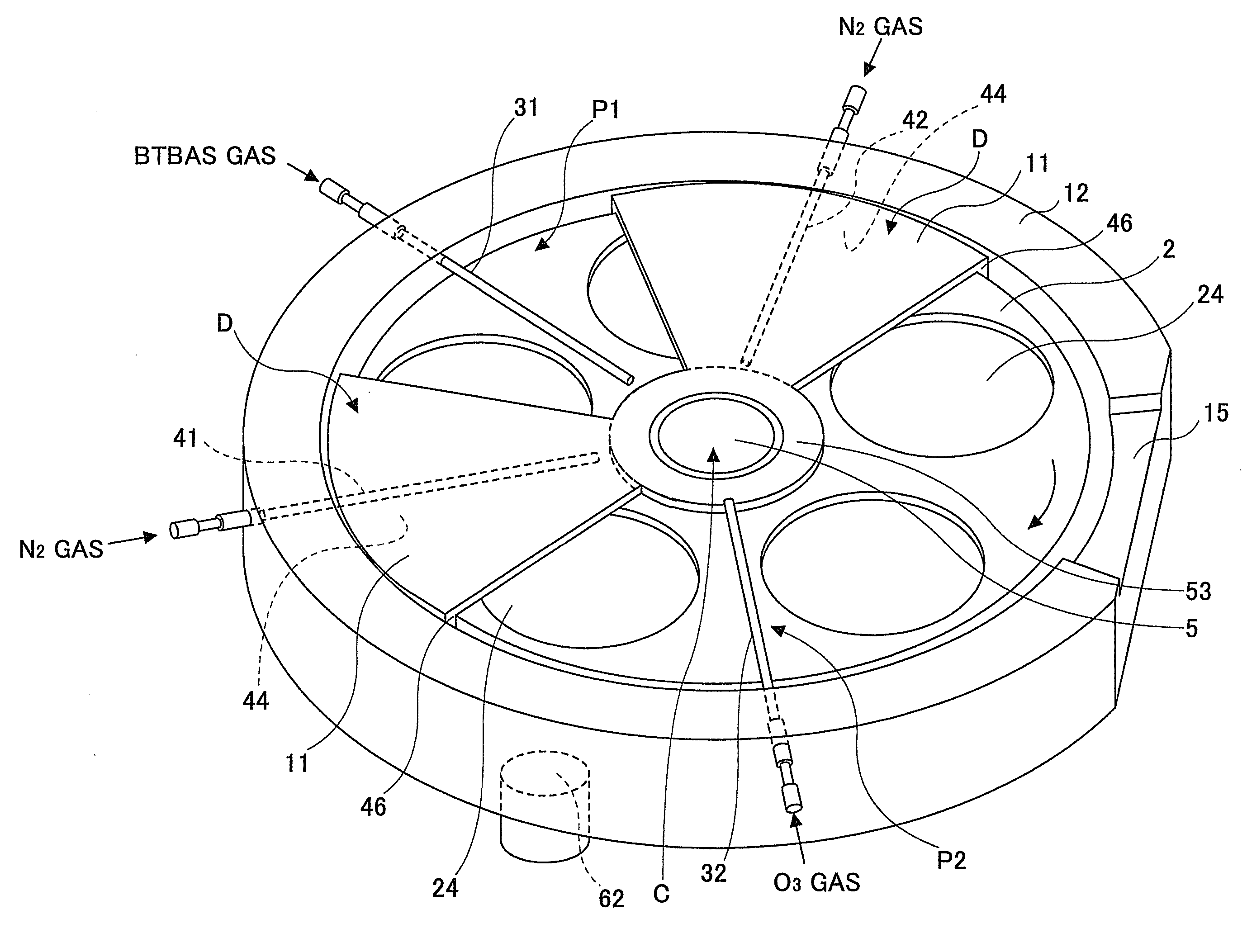
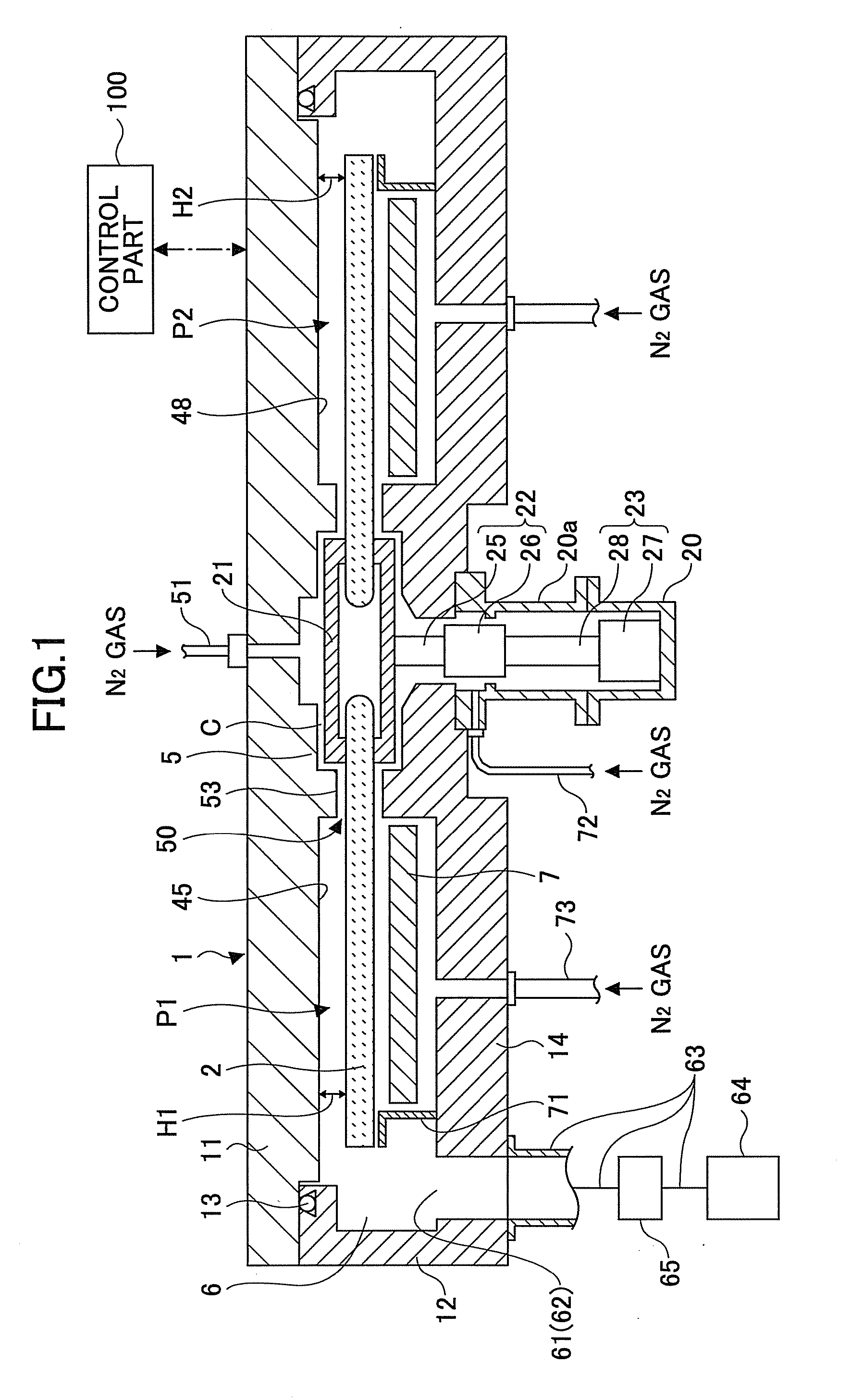
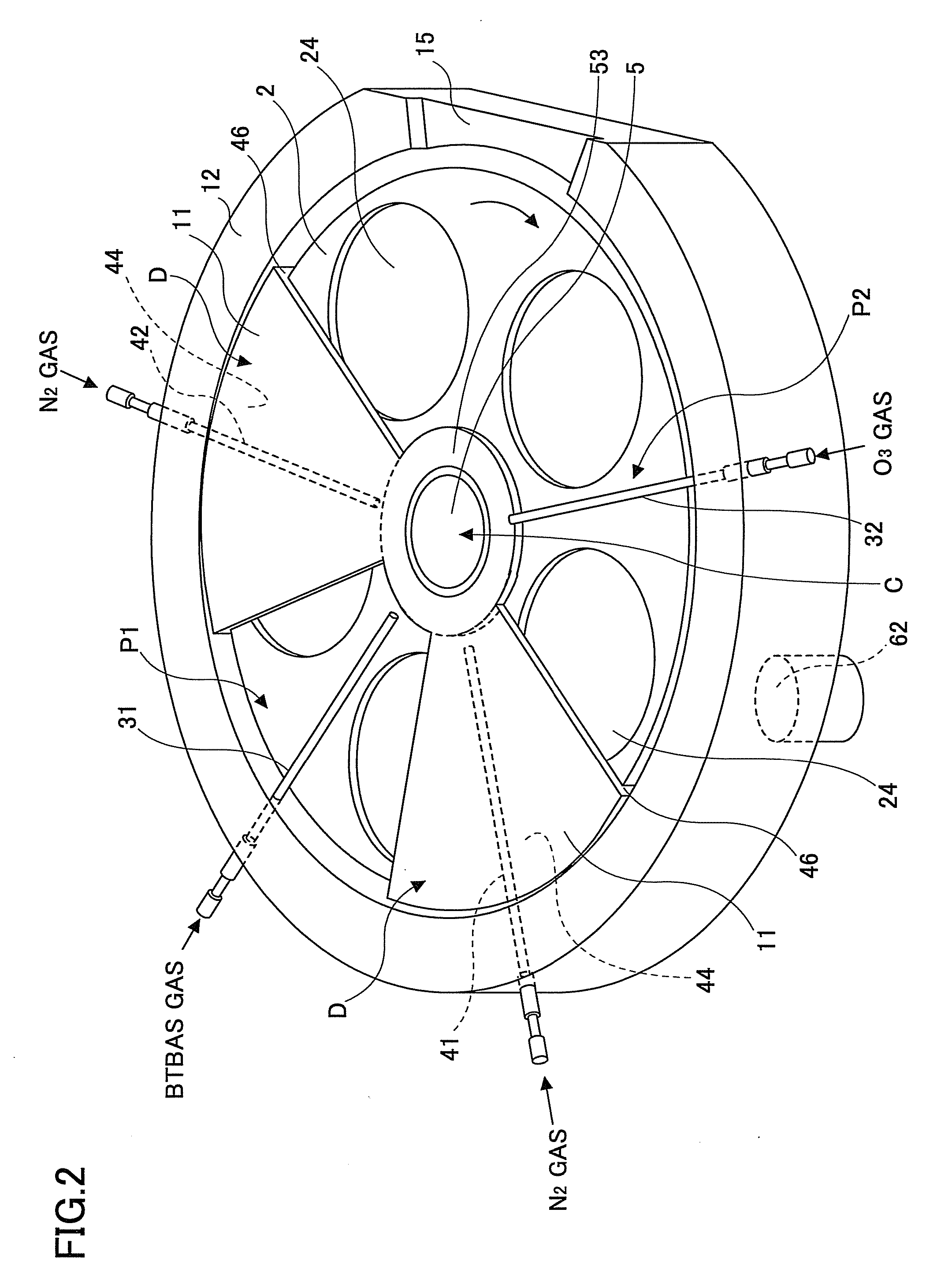
[0062]A description will now be given, with reference to FIG. 1 through FIG. 13, of a film deposition apparatus and a film deposition method according to a first embodiment of the present invention. First, a description is given, with reference to FIG. 1 through FIG. 12, of a structure of the film deposition apparatus according to the first embodiment of the present invention. As illustrated in FIG. 1 through FIG. 3, the film deposition apparatus according to the present embodiment includes a vacuum chamber 1, a turntable 2, a first reaction gas supply part 31, a second reaction gas supply part 32, and first separation gas supply parts 41 and 42. The vacuum chamber 1 has a ceiling plate 11a chamber body 12, an O-ring 13, and a bottom part 14. The ceiling plate 11 is detachably attached to the chamber body 12. The ceiling plate 11 is pressed against the chamber body 12 via the O-ring 13 due to depressurization inside the vacuum chamber in order to maintain an airtight state. When sep...


PUM

PropertyMeasurementUnit
widthaaaaaaaaaa
distanceaaaaaaaaaa
vortex angleaaaaaaaaaa

Abstract

A film deposition apparatus includes: a turntable; a first reaction gas supply part and a second reaction gas supply part extending from a circumferential edge toward a rotation center of the turntable; and a first separation gas supply part provided between the first and second reaction gas supply parts. A first space contains the first reaction gas supply part and has a first height. A second space contains the second reaction gas supply part and has a second height. A third space contains a first separation gas supply part and has a height lower than the first and second heights. A motor provided under the rotation center of the turntable rotates the turntable. A rotation shaft of the turntable and a drive shaft of the motor are coupled without generation of slip.

Description

CROSS-REFERENCE TO RELATED APPLICATIONS[0001]This application is based upon and claims the benefit of priority of the prior Japanese Patent Application No. 2008-227028, filed on Sep. 4, 2009, the entire contents of which are incorporated herein by reference.BACKGROUND OF THE INVENTION[0002]1. Field of the Invention[0003]The present invention relates to film deposition apparatuses and substrate processing apparatuses and, more particularly, to a film deposition apparatus and a substrate processing apparatus for depositing a thin film by alternately supplying at least two kinds of source gases.[0004]2. Description of the Related Art[0005]As a film deposition technique in a semiconductor fabrication process, there has been known a so-called Atomic Layer Deposition (ALD) or Molecular Layer Deposition (MLD). In such a film deposition technique, a first reaction gas is adsorbed on a surface of a semiconductor wafer (referred to as a wafer hereinafter) under vacuum and then a second reacti...

Claims


Application Information

Patent Timeline
Patent Type & Authority Applications(United States)
IPC IPC(8): C23C16/458
CPCC23C16/401C23C16/45508C23C16/4583C23C16/45551C23C16/45502H01L21/20
Inventor KATO, HITOSHIHONMA, MANABUHANEISHI, TOMOKI
Owner TOKYO ELECTRON LTD
Why Eureka
Try Eureka