Method and apparatus for detecting and discriminating particles in a fluid

a particle detection and fluid technology, applied in the direction of optical radiation measurement, luminescent dosimeter, instruments, etc., can solve the problems of high voltage (about 1000 volts) for proper operation, voltages can be dangerous to people, and require protective measures, so as to improve detection versatility, reduce cost, and improve detection efficiency

Inactive Publication Date: 2010-03-04
MASSACHUSETTS INST OF TECH
View PDF6 Cites 21 Cited by
  • Summary
  • Abstract
  • Description
  • Claims
  • Application Information

AI Technical Summary

Benefits of technology

[0005]Existing flow cytometer systems tightly confine the particle flow stream in order to ensure optimal particle illumination and detection of particle radiation. In addition these systems detect only one particle at a time. This tight flow confinement and one particle at a time detection methodology substantially limit the fluid flow rate and the number of particles that can be interrogated per unit time.
[0006]A system and method for particle detection, according to example embodiments of the present invention, is presented. This system utilizes detector arrays for detecting the light emission from particles in a flow stream and may also utilize light source arrays for selective illumination of the particles. Each ...

Problems solved by technology

While photomultiplier tube (PMT) devices are often the ideal photodetector for low light applications there are a few drawbacks associated with their use.
First PMTs are relatively expensive as compared with other types of photodetectors such as the semiconductor photodiode or charged coupled device (CCD) detector.
Second, PMTs typically require high voltage (about 1000 Volts) for proper operation.
Such ...

Method used


Image

  • Method and apparatus for detecting and discriminating particles in a fluid
  • Method and apparatus for detecting and discriminating particles in a fluid
  • Method and apparatus for detecting and discriminating particles in a fluid

Examples


Embodiment Construction

[0026]A description of example embodiments of the invention follows.

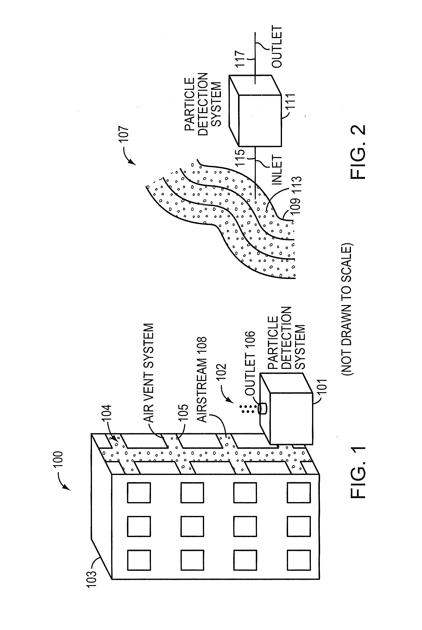
[0027]FIG. 1 provides an example 100 of a particle detection system 101. The particle detection system 101 may be situated to detect particles 104 in an air vent system 105 of a building 103. The particle detection system 101 includes an inlet (not shown) in which an airflow enters the particle detection system 101. An outlet 106 may be used as a pathway to shunt the airflow from the detection system 101. The detection system 101 may be used to control air duct valves within the building in order close off the building from outside air or from other parts of the building if particles 102 detected are deemed unsafe for breathing.

[0028]As another example, a liquid stream may also need to be evaluated. For instance, a water reservoir may need to be continuously monitored to ensure harmful particles are not introduced into a water supply.

[0029]FIG. 2 provides an example 107 of a particle detection system 111 detecting p...


PUM


Abstract

A particle detection system that images and detects particles in a fluid flow stream through use of detector array(s) is described. The detection system may include light source arrays that may selectively illuminate a particle in a fluid stream. The detection system may also include a detector array employing smart binning to read the measured signals. The smart binning of the detector array may be achieved through knowledge of an exact particle location provided by a position sensitive detector. The detector array(s) may be low cost based on intelligence built into the system. This particle detection system may be particularly useful for detection and discrimination of different particle types since the read-out of the particle signals can be accomplished with low noise and can be flexible enough to optimize the read out measurements for each particle. The particle detection system may be used, for example, in early warning contamination detection systems and manufacturing processes.

Description

RELATED APPLICATION[0001]This application is related to U.S. application Ser. No. 11 / 804,593, filed May 18, 2007, which claims the benefit of U.S. Provisional Application No. 60 / 802,088, filed on May 18, 2006. The entire teachings of the above applications are incorporated herein by reference.GOVERNMENT SUPPORT[0002]The invention was supported, in whole or in part, by a grant FA8721-05-C-0002 from the United States Air Force. The Government has certain rights in the invention.BACKGROUND OF THE INVENTION[0003]An ability to detect and classify small particles in a fluid stream (air or liquid) is of great use in many fields. For example, detecting harmful particles in air (e.g., outdoors or inside a building) or in water (e.g., a city water supply) may be used to protect people from non-lethal particles, such as mold spores, or lethal particles, such biological agent particles. In addition, a large class of particle detector systems referred to as flow cytometers are based on the detec...

Claims


Application Information

Patent Timeline
IPC IPC(8): G01N21/47G01N21/85
CPCG01N15/1425G01N15/1434G01N2015/145G01N2015/025G01N2015/1075G01N15/1459
Inventor JEYS, THOMAS H.SANCHEZ-RUBIO, ANTONIOMOLNAR, RICHARD J.REICH, ROBERT K.RANKA, JINENDRA K.SPEARS, DAVID L.OSGOOD, III, RICHARD M.
Owner MASSACHUSETTS INST OF TECH
Why Eureka
Try Eureka