Film deposition apparatus, substrate processing apparatus, film deposition method, and computer-readable storage medium

a technology of substrate processing and film deposition, which is applied in the direction of vacuum evaporation coating, chemical vapor deposition coating, coating, etc., can solve the problems of contaminating the wafer, the curtain cannot completely, and the process time is long, so as to achieve the effect of accurate detection and sufficient rotational position accuracy

Inactive Publication Date: 2010-03-04
TOKYO ELECTRON LTD
View PDF5 Cites 436 Cited by
  • Summary
  • Abstract
  • Description
  • Claims
  • Application Information

AI Technical Summary

Benefits of technology

[0031]In an aspect of this disclosure, there is provided a film deposition apparatus and a film deposition method which carry out appropriate film deposition processing without jeopardizing high production throughput, by performing plural cycles of alternately supplying plural reactive gases to the substrate to form plural layers of the reaction products of the reactive gase

Problems solved by technology

When such a deposition chamber is used, it takes a long time for a purge gas to purge the reactive gases, resulting in an extremely long process time because the number of cycles may reach several hundred.
However, because the reactive gases and the separation gas are supplied downward and then evacuated upward from the evacuation ports provided at the upper portion of the chamber, particles in the chamber may be blown upward by the upward flow of the gases and fall on the wafers, leading to contamination of the wafers.
However, the gas curtain cannot completely prevent mixture of the reactive gases but may allow one of the reactive gases to flow through the gas curtain to be mixed with the other reactive gas partly because the gases flow along the rotation direction due to the rotation of the wafer support member.
Therefore, ALD (or MLD) mode deposition cannot be carried out in a proper manner by this process chamber.
However, Patent Document 4 does not provide any realistic measures to prevent two source gases (AsH3, TMG) from being mixed.
Moreover, because the evacuation ports are located between the adjacent two gas supplying plates to evacua

Method used


Image

  • Film deposition apparatus, substrate processing apparatus, film deposition method, and computer-readable storage medium
  • Film deposition apparatus, substrate processing apparatus, film deposition method, and computer-readable storage medium
  • Film deposition apparatus, substrate processing apparatus, film deposition method, and computer-readable storage medium

Examples


first embodiment

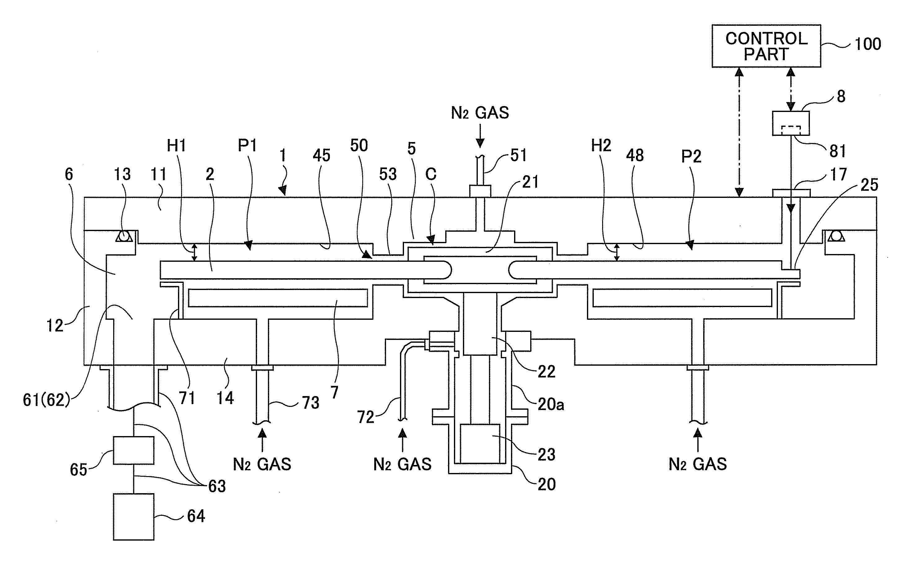
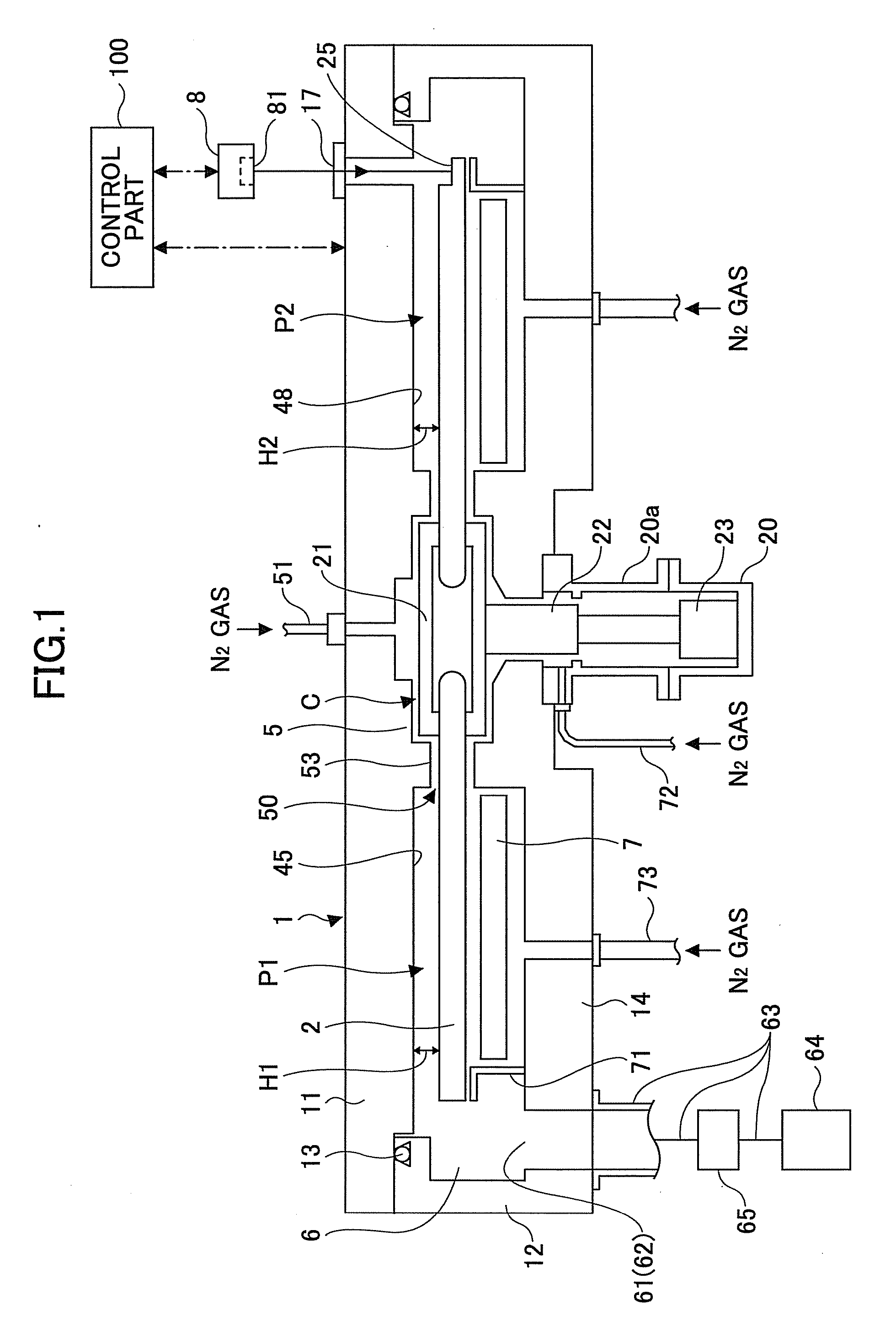
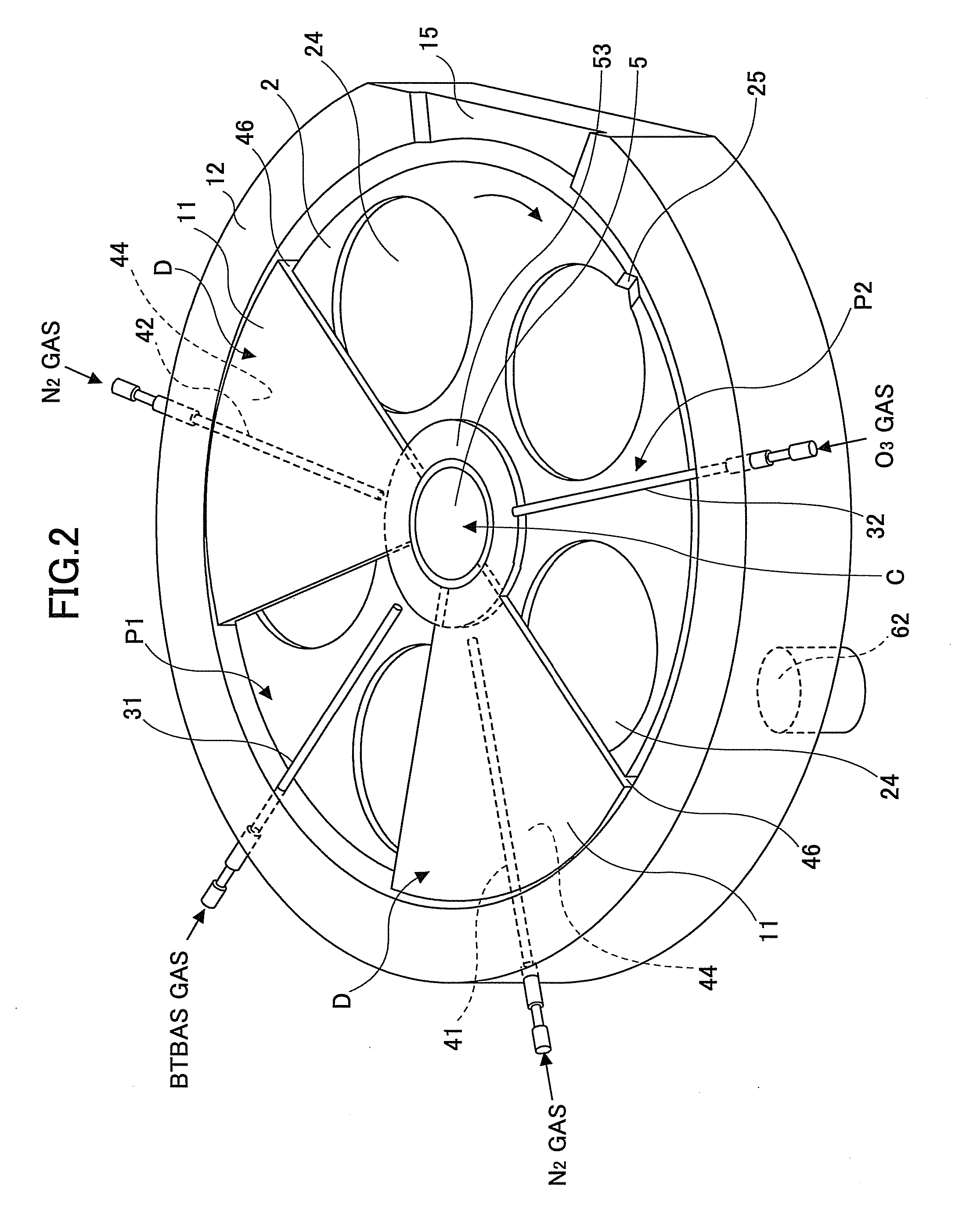
[0079]Referring to FIGS. 1 through 12, the composition of a film deposition apparatus of the invention will be described. The cross section of the film deposition apparatus of this embodiment illustrated in FIG. 1 is taken along line B-B indicated in FIG. 3.

[0080]As illustrated in FIGS. 1 through 3, the film deposition apparatus of this embodiment includes a vacuum chamber 1, a turntable 2, a first reactive gas supplying portion 31, a second reactive gas supplying portion 32, first separation gas supplying portions 41 and 42, and a laser sensor 8. The laser sensor 8 corresponds to a position detecting unit in the claims.

[0081]As illustrated in FIGS. 1 through 3, the vacuum chamber 1 is a flattened container component having a generally circular configuration. The vacuum chamber 1 includes a top plate 11, a container main part 12, an O ring 13, and a base part 14.

[0082]The top plate 11 is arranged so that the top plate 11 may be separated from the container main part 12. The top plat...

second embodiment

[0344]Next, with reference to FIG. 41, a substrate processing apparatus of the invention will be described. FIG. 41 is a plan view illustrating the composition of the substrate processing apparatus of this embodiment.

[0345]As illustrated in FIG. 41, the substrate processing apparatus of this embodiment includes a conveyance container 101, an atmosphere conveyance chamber 102, a conveyance arm 103, load lock chambers 104 and 105 (which constitute a reserve vacuum chamber in the claims), a vacuum conveyance chamber 106, a conveyance arm 107, and film deposition apparatuses 108 and 109.

[0346]The conveyance container 101 is a hermetically sealed conveyance container (called FOUP) which stores 25 wafers, for example. The atmosphere conveyance chamber 102 is an air conveyance chamber in which the conveyance arm 103 is arranged.

[0347]Each of the load lock chambers 104 and 105 is arranged to switch the internal atmosphere of the chamber between an air atmosphere and a vacuum atmosphere.

[034...


PUM

PropertyMeasurementUnit
Widthaaaaaaaaaa
Areaaaaaaaaaaa
Depthaaaaaaaaaa

Abstract

In a film deposition apparatus which deposits a thin film on a substrate by supplying first and second reactive gases in a vacuum chamber, there are provided a turntable, a first reactive gas supplying portion and a second reactive gas supplying portion which are arranged to extend from circumferential positions of the turntable to a center of rotation of the turntable, a first separation gas supplying portion arranged between the first and second reactive gas supplying portions, a first space having a first height and including the first separation gas supplying portion, a second space having a second height and including the second reactive gas supplying portion, a third space having a height lower than the first height and the second height and including the first separation gas supplying portion, a position detecting unit detecting a rotation position of the turntable, and a detection part arranged at a circumferential portion of the turntable and detected by the position detecting unit.

Description

CROSS-REFERENCE TO RELATED APPLICATION[0001]This application is based upon and claims the benefit of priority from Japanese patent application No. 2008-227031, filed on Sep. 4, 2008, and Japanese patent application No. 2009-133153, filed on Jun. 2, 2009, the entire contents of which are incorporated herein by reference in their entirety.BACKGROUND OF THE INVENTION[0002]1. Field of the Invention[0003]This invention relates to a film deposition apparatus, a substrate processing apparatus, a film deposition method, and a computer-readable storage medium for depositing a film on a substrate by alternately supplying two or more source gases to the substrate.[0004]2. Description of the Related Art[0005]As a film deposition technique in a semiconductor fabrication process, there has been known a so-called Atomic Layer Deposition (ALD) or Molecular Layer Deposition (MLD). In such a film deposition technique, a first reactive gas is adsorbed on a surface of a semiconductor wafer (referred to...

Claims


Application Information

Patent Timeline
IPC IPC(8): C23C16/455B05C11/00
CPCC23C16/45502C23C16/45508C23C16/52C23C16/4585C23C16/45551C23C16/00H01L21/02H01L21/205
Inventor KATO, HITOSHIHONMA, MANABUHANEISHI, TOMOKIAIKAWA, KATSUYOSHI
Owner TOKYO ELECTRON LTD
Why Eureka
Try Eureka