
Plasma display panel

a technology of display panel and plasma, which is applied in the manufacture of electrode systems, electric discharge tubes/lamps, gas exhaustion means, etc., can solve the problems of weak resistance to water, change in trend, and difficulty in maintaining the airtight state of a pdp sufficiently, and achieves high reliability

Inactive Publication Date: 2010-03-11
PANASONIC CORP
View PDF10 Cites 5 Cited by
  • Summary
  • Abstract
  • Description
  • Claims
  • Application Information

AI Technical Summary

Benefits of technology

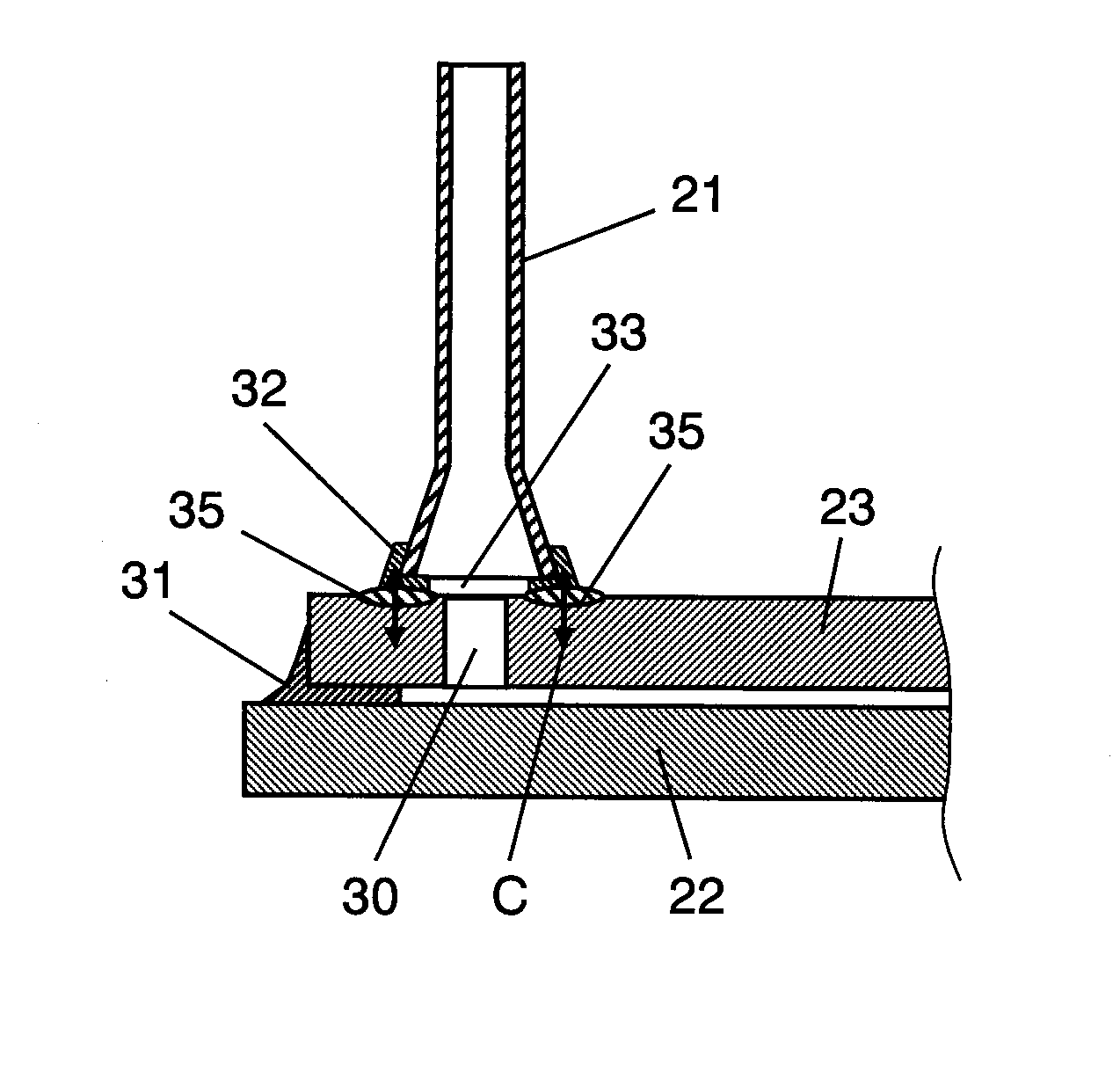
[0017]Thus, since an adjustment is made such that the tension works on the sealed part, the sealed part is not damaged by cracking or the airtight state of the sealed part does not deteriorate, and accordingly, the high reliability is secured. As a result, it is possible to realize a high-quality PDP in which an environmental problem is considered due to using a non-lead material.

Problems solved by technology

However, in the case of sealant having phosphate-tin oxide based low-melting-point glass as a main component that has been proposed as non-lead sealant, a resistance to water is weak as compared with lead oxide based sealant that has been used in the related art.
Accordingly, there is a problem in that it is difficult to sufficiently maintain the airtight state of a PDP.
However, due to an environmental issue, a trend is changing in the direction in which borosilicate based glass not containing lead is used.
Accordingly, a problem occurs in that crack damage occurs or the airtight state deteriorates to cause leak failure.
As the temperature in sealing processing increases, distortion resulting from a stress occurs noticeably, which also increases a failure frequency in a manufacturing process.

Method used


Image

  • Plasma display panel
  • Plasma display panel
  • Plasma display panel

Examples


Embodiment Construction

[0054]Hereinafter, a PDP according to an embodiment of the invention will be described in detail with reference to the accompanying drawings.

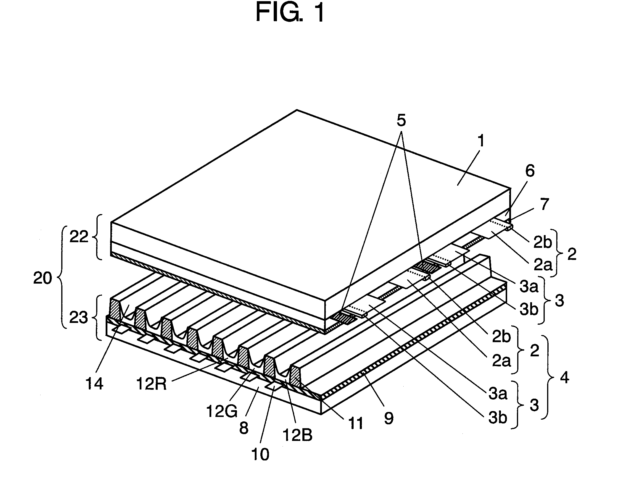
[0055]FIG. 1 is a perspective view illustrating the structure of a PDP according to an embodiment of the invention. The basic structure of the PDP is the same as that of a general alternating-current surface discharge type PDP. As shown in FIG. 1, in PDP 20, front plate 22 having front glass substrate 1 and the like and rear plate 23 having rear glass substrate 8 and the like are disposed opposite to each other and peripheries of front plate 22 and rear plate 23 are airtight sealed by sealant, such as glass frit. In a discharge space 14 inside sealed PDP 20, discharge gas, such as neon (Ne) and xenon (Xe), is filled at a pressure of 53200 Pa to 79800 Pa.

[0056]On front glass substrate 1 of front plate 22, a plurality of strip-shaped display electrodes 4, each of which includes a pair of scan electrode 2 and sustain electrode 3, and a plurality o...


PUM

PropertyMeasurementUnit
Temperatureaaaaaaaaaa

Abstract

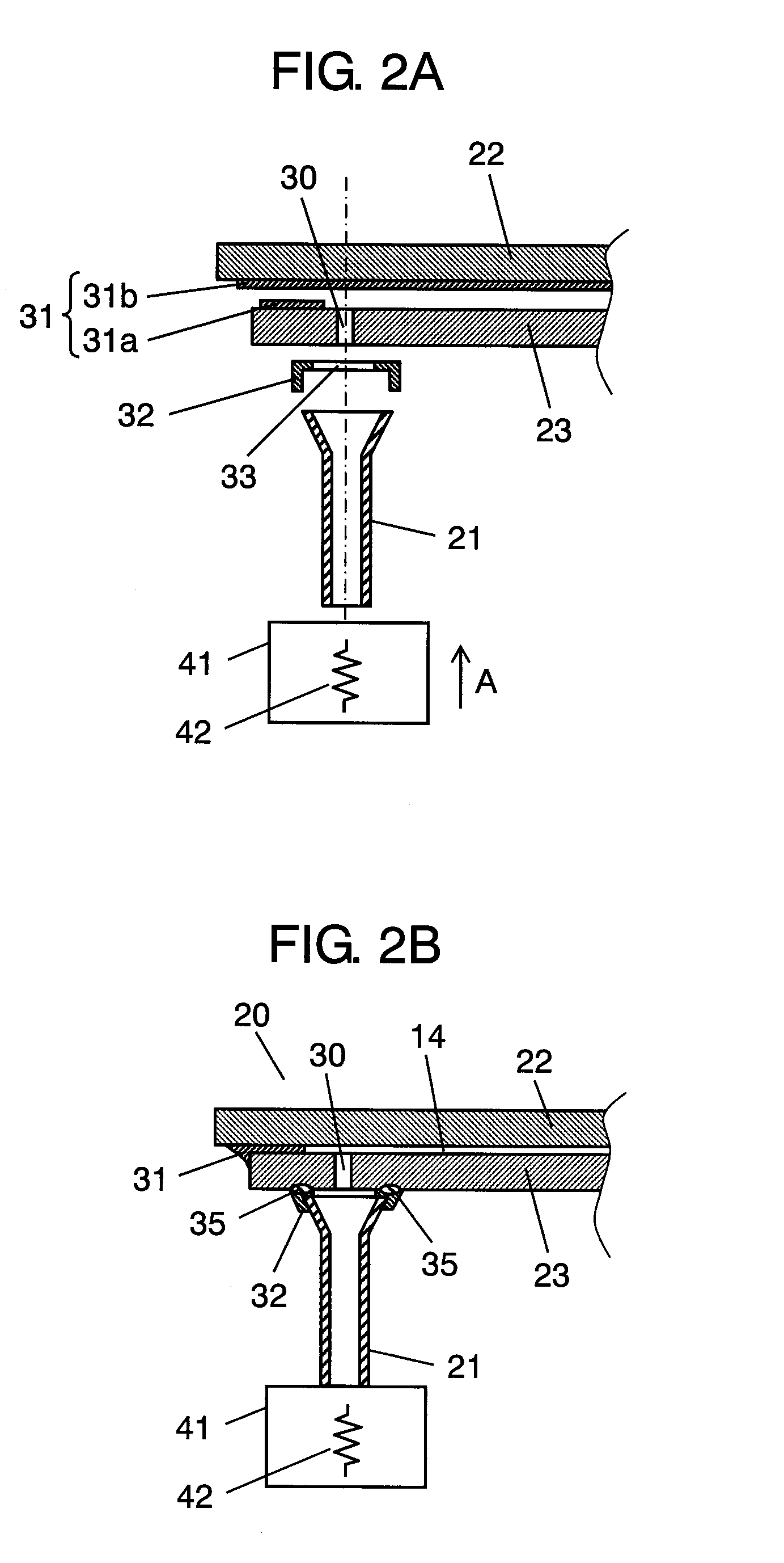
There is provided a plasma display panel in which a front plate and a rear plate are disposed opposite to each other, a side of a tubular exhaust pipe is disposed in the vicinity of a fine hole provided in the rear plate using a tablet serving as sealant formed of frit glass, peripheries of the front plate and the rear plate and the exhaust pipe are sealed with the sealant in order to form a discharge space, and the discharge space is ventilated and discharge gas is filled into the discharge space through the exhaust pipe. The rear plate and the exhaust pipe are sealed by a sealed part obtained by melting a tablet made of amorphous frit glass not containing lead, and a stress working on the sealed part is a tension in the direction of the rear plate and the direction of the exhaust pipe.

Description

TECHNICAL FIELD[0001]The present invention relates to a plasma display panel (hereinafter, referred to as ‘PDP’) that is a flat display device used in a large-sized television, a public display, and the like.BACKGROUND ART[0002]As high resolution and large screen in a PDP are realized, a 65-inch television receiver or a large-sized public display device is being manufactured and a product larger than 100 inch is also planned. Particularly in the case of a PDP dedicated for a television receiver, application to full spec Hi-Vision, in which the number of scan lines is twice or more than that in the known NTSC system, is under progress.[0003]Basically, a PDP is configured to include a front plate and a rear plate. The front panel is configured to include a glass substrate made of sodium borosilicate based glass using a float method, display electrodes including strip-shaped transparent electrodes and bus electrodes formed on a main surface of the glass substrate, a dielectric layer th...

Claims


Application Information

Patent Timeline
IPC IPC(8): H01J61/30H01J11/46H01J11/48H01J11/54
CPCH01J9/385H01J11/54H01J11/12C03C3/066C03C8/24H01J1/54
Inventor NISHINAKA, MASAKIMIYAZAKI, AKINOBU
Owner PANASONIC CORP
Learn More